3-54 Programming and Parameters
INPUTS & OUTPUTS
Analog Inputs
322
325
[Analog In 1 Hi]
[Analog In 2 Hi]
Sets the highest input value to the analog
input x scaling block.
[Anlg In Config], parameter 320 defines if
this input will be –/+10V or 4-20 mA (0-20
mA with Vector firmware 3.xxx & later).
Default:
Min/Max:
Units:
10.000 Volt
10.000 Volt
4.000/20.000mA
0.000/20.000mA
–/+10.000V
0.000/10.000V
0.001 mA
0.001 Volt
091
092
323
326
[Analog In 1 Lo]
[Analog In 2 Lo]
Sets the lowest input value to the analog
input x scaling block.
[Anlg In Config], parameter 320 defines if
this input will be –/+10V or 4-20 mA (0-20
mA with Vector firmware 3.xxx & later).
If set below 4 mA, [Analog In x Loss]
should be “Disabled.”
Default:
Min/Max:
Units:
0.000 Volt
0.000 Volt
4.000/20.000mA
0.000/20.000mA
–/+10.000V
0.000/10.000V
0.001 mA
0.001 Volt
091
092
324
327
[Analog In 1 Loss]
[Analog In 2 Loss]
Selects drive action when an analog
signal loss is detected. Signal loss is
defined as an analog signal less than 1V
or 2mA. The signal loss event ends and
normal operation resumes when the
input signal level is greater than or equal
to 1.5V or 3mA.
Default:
Options:
0
0
0
1
2
3
4
5
6
“Disabled”
“Disabled”
“Disabled”
“Fault”
“Hold Input”
“Set Input Lo”
“Set Input Hi”
“Goto Preset1”
“Hold OutFreq”
091
092
Analog Outputs
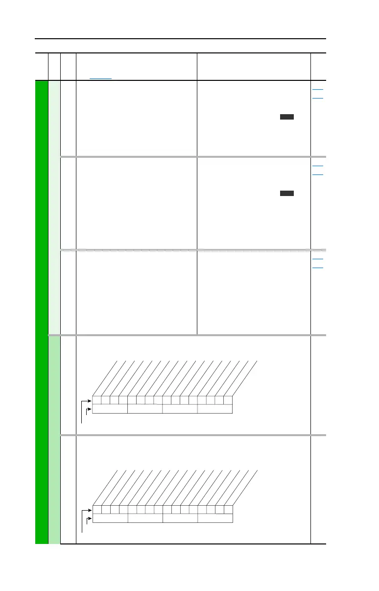
340 [Anlg Out Config]
Selects the mode for the analog outputs. .
341 [Anlg Out Absolut]
Selects whether the signed value or absolute value of a parameter is used before
being scaled to drive the analog output.
File
Group
No.
Parameter Name & Description
See page 3-2 for symbol descriptions
Values
Related
v3
v3
1xx 1xxxxxxxxxxxx
10 01234567891112131415
1 =Current
0 =Voltage
x =Reserved
Bit # * Vector Control Option Only
Factory Default Bit Values
Analog Out1
Analog Out2 *
1xx 1xxxxxxxxxxxx
10 01234567891112131415
1 =Absolute
0 =Signed
x =Reserved
Bit #
Factory Default Bit Values
Analog Out1
Analog Out2 *
* Vector Control Option Only
 Loading...


