16 Rockwell Automation Publication 750-IN020D-EN-P - May 2017
PowerFlex 755 IP00, NEMA/UL Open Type Drive
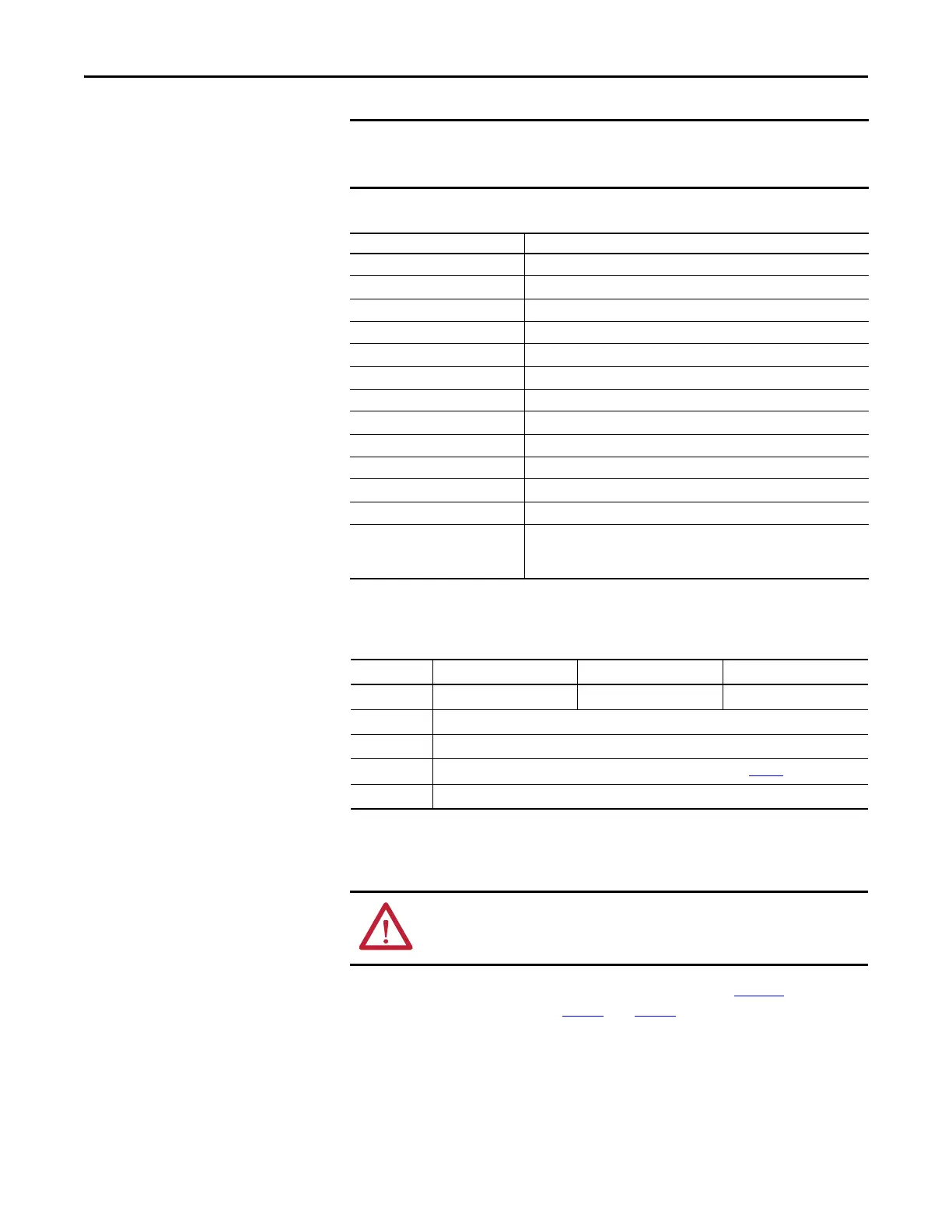
Installation Tools
This list covers the tools needed for drive installation.
Enclosure Requirements
The following specifications must be met for proper installation.
Bus Bars
Power wiring is connected to the drive power terminals (see page 47) using the
Field Termination kits shown on page 6
and page 7 or fabricated using material
with the following specifications:
• Material: CDA 110 Copper
• Minimum Cross Section: 80.7mm
2
(0.125
in.
2
) per each 100 A of drive
rating.
Care must be taken to ensure that tools and/or hardware components do not fall into
open drive assemblies. Do not energize the drive unless all loose tools and/or hardware
components have been removed from the drive assemblies and enclosure.
Tool Description Details
ESD-protected place of work Working surface, Floor covering, seat and ground connections
ESD-protective clothing Wrist wrap, shoes, overall clothing (coat)
Allen socket wrench 5 mm
Allen socket wrench extension 254 mm (10 in.)
Flat nose screw driver 5 mm (0.19 in.), 6.4 mm (0.25 in.), 9.5 mm (0.375 in.), #1, #2
Hexalobular screw driver/bit #15, #20, #25, #40, #45
Hexagonal socket wrench 7 mm, 8 mm, 10 mm, 12 mm, 13 mm, 17 mm, 18 mm
Combination wrench 10 mm, 17 mm
Phillips screw driver/bit #2, 492-C
Pozidriv #2
Torque wrench 1...12 N•m (8.8…106 lb•in)
Torque wrench 6...50 N•m (53…443 lb•in)
Roll-out cart 20-750-CART1-F8
Note: The roll-out cart is required to remove the drive assembly from the
enclosure.
Frame 8Frame 9Frame 10
Width 800 mm (31.5 in.) min. 1600 mm (63.0 in.) min. 2400 mm (94.5 in.) min.
Depth 600 mm (23.6 in.) min.
Height 2200 mm (86.6 in.) min.
Weight Enclosure must be able to support the total equipment weight stated on page 36
.
Construction According to EN60439-1
ATTENTION: To guard against drive damage, DO NOT connect power wires
directly to the drive power terminals. Power wiring must be connected to bus
bars which are fastened to the drive power terminals.
 Loading...


