Rockwell Automation Publication 750-IN020D-EN-P - May 2017 47
PowerFlex 755 IP00, NEMA/UL Open Type Drive
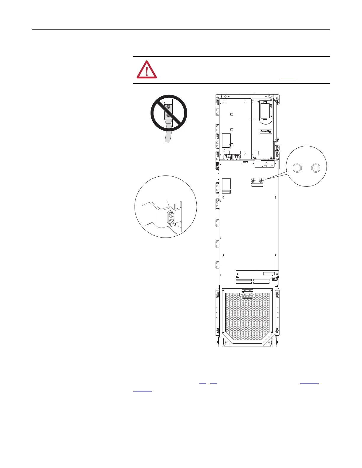
Power Terminals
For easier power wiring, movable L-bracket assemblies are included with the
Field Termination kits to connect the AC line input, output to the motor, and
DC bus power. Arrange the moveable L-brackets and secure using the torque
guidelines listed. See pages 49
…57 for kit installation guidelines and page 39 or
page 40
for recommended mounting locations and dimensions.
ATTENTION: To guard against drive damage, Do Not connect power wires
directly to the drive power terminals. Power wiring must be connected to bus
bars which are fastened to the drive power terminals. See page 16
.
W/T3
V/T2
U/T1
-DC
+DC
T/L3
S/L2
R/L1
TESTPOINTS
DC- DC+
TESTPOINTS
DC- DC+
Inverter/Converter
Assembly Shown
Do Not connect field
wiring directly to power
terminals
Bus Bar to Power
Terminal Detail
M10 x 35 mm SEMS
Torque: 22.4 N•m
(200 lb•in)
 Loading...


