26 Rockwell Automation Publication 750-IN020D-EN-P - May 2017
PowerFlex 755 IP00, NEMA/UL Open Type Drive
Horizontal Mounting
Guidelines – Single Drive
Unit Only
To guard against sub-panel flexing, support pieces should be added to the
underside of the panel along each long edge.
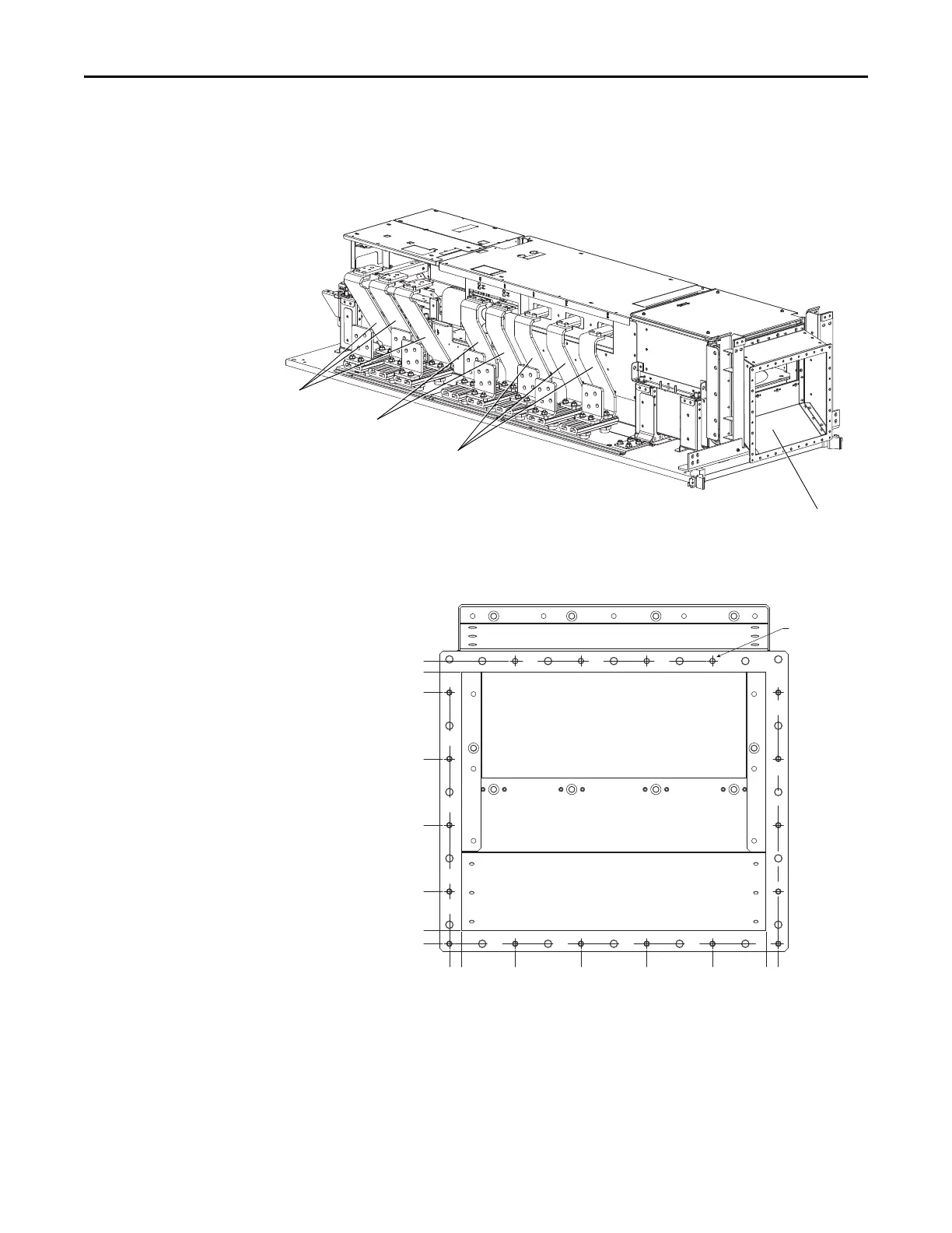
Figure 8 - Open Style Drive - Horizontal Installation
Figure 9 - Bottom Inlet Ducting Kit Dimensions
Bottom Inlet Duct Kit
Converter (AC Input) Field
Termination Kit
Inverter (AC Output) Field
Termination Kit
Optional Inverter (DC Bus)
Field Termination Kit
325.00 (12.795)
M6 x 1 - 18 places
312.00 (12.283)
287.00 (11.299)
207.00 (8.150)
127.00 (5.000)
47.00 (1.850)
0.00 (0.000)
16.00 (0.630)
15.00 (0.591)
0.00 (0.000)
64.40 (2.535)
143.80 (5.661)
223.20 (8.787)
302.60 (11.913)
382.00 (15.039)
367.00 (14.450)
 Loading...


