58 Rockwell Automation Publication 750-IN020D-EN-P - May 2017
PowerFlex 755 IP00, NEMA/UL Open Type Drive
Cable Routing
Control Pod Cable Routing
Supports, clips, and cable ties are provided to help route and secure cabling inside
the Control Pod.
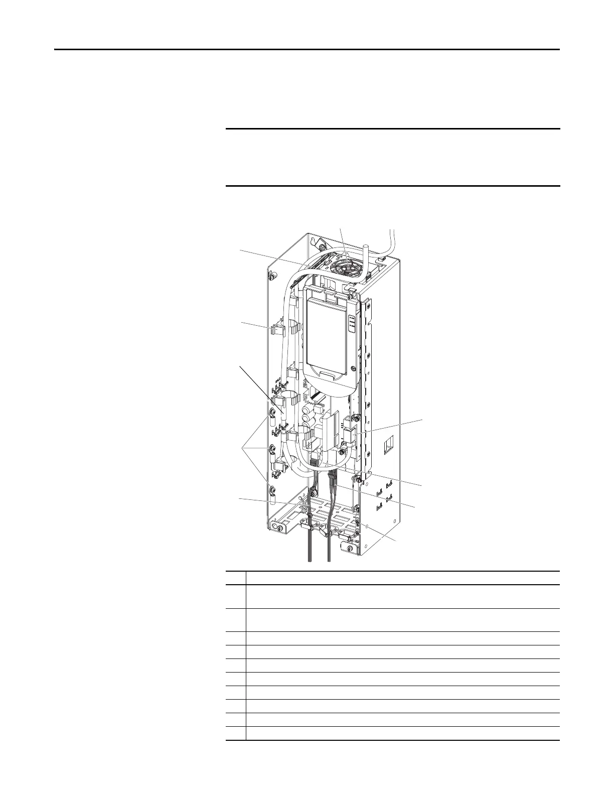
Figure 20 - Frame 8 Control POD Detail
• When routing cabling into the control Pod, do not block the cooling fan
outlet.
• Do not ground shield wires to inner sheet metal bucket supporting option
modules.
No. Description
1 I/O signal cable shield termination points. Use M4 screws and ring terminals provided to tie together and
terminate drain wires and shields.
2 Ground shield wires to outer sheet metal bucket. Strip cable insulation 25 mm (1 in.) to expose braid. Attach cable
ties around shield and through slots. Pull tight.
3 Attachment points for cable management devices provided (6 places).
4 Cable support ladder.
5 Fan outlet. Keep clear to help ensure proper cooling.
6 Control cable entry and routing.
7 Human Interface Module (HIM) cable entry and routing.
8 Shield termination points.
9 Inverter Fiber-optic connection
10 Internal 24V power connection
 Loading...


