Rockwell Automation Publication 750-QS001A-EN-P - March 2015 11
Step 2: Validate the Drive Installation
Refer to the diagram on page 10 for item number locations.
Verify the status of the enable jumper and the safety jumper.
• If the enable jumper is removed, control power is required at Di0 on the main control board for the drive to be
able to
accept a Start command. See parameter 220 [Digital In Sts] bit 0. For more information, see PowerFlex
750-Series AC Drive Installation Instructions, publication
750-IN001.
• If the safety jumper is removed, see Safe Speed Monitor Option Module for PowerFlex 750-Series AC Drives
Safety
Reference Manual, publication
750-RM001 for catalog number 20-750-S1 and PowerFlex 750-Series
Safe-Torque Off User Manual, publication
750-UM002 for catalog number 20-750-S.
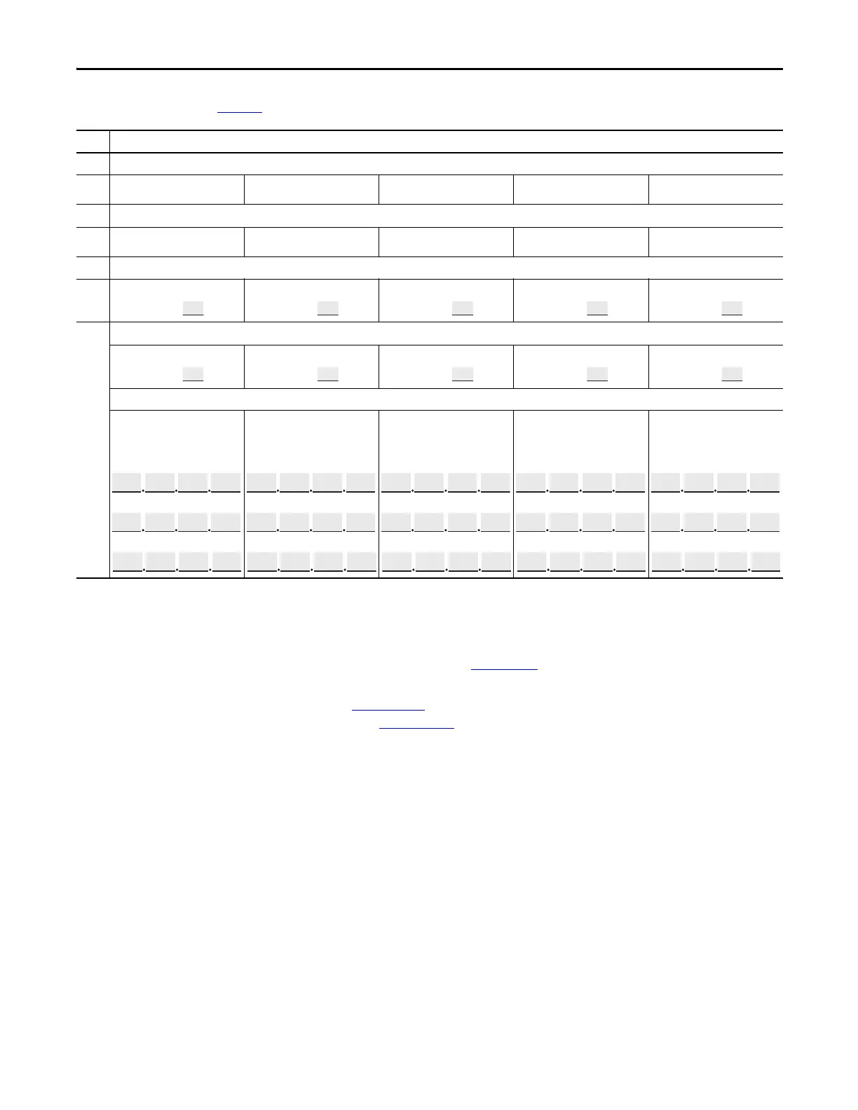
Item
(1) Are signal sources connected to terminal block TB1 on your PowerFlex 753 drive?
Drive 1:
❑ Yes ❑ No Drive 2: ❑ Yes ❑ No Drive 3: ❑ Yes ❑ No Drive 4: ❑ Yes ❑ No Drive 5: ❑ Yes ❑ No
(2) Is there a connection to the Embedded EtherNet/IP port on your PowerFlex 755 drive?
Drive 1:
❑ Yes ❑ No Drive 2: ❑ Yes ❑ No Drive 3: ❑ Yes ❑ No Drive 4: ❑ Yes ❑ No Drive 5: ❑ Yes ❑ No
(3) Are signal sources connected to an expansion I/O module installed in your drive? If yes, note the module’s port number.
Drive 1:
❑ Yes: Port No. ❑ No
Drive 2:
❑ Yes: Port No. ❑ No
Drive 3:
❑ Yes: Port No. ❑ No
Drive 4:
❑ Yes: Port No. ❑ No
Drive 5:
❑ Yes: Port No. ❑ No
(4) Are signal sources connected to a communication network module installed in your PowerFlex 753 drive? If yes, note the module’s port number.
Drive 1:
❑ Yes: Port No. ❑ No
Drive 2:
❑ Yes: Port No. ❑ No
Drive 3:
❑ Yes: Port No. ❑ No
Drive 4:
❑ Yes: Port No. ❑ No
Drive 5:
❑ Yes: Port No. ❑ No
Which EtherNet/IP configuration is your drive using (BOOTP, DHCP, or ma
nual IP address)? If using a manual IP address, enter the IP address and the subnet address.
Drive 1:
❑ BOOTP ❑ DHCP
❑ Manual
IP Address
Subnet Mask (if required)
Gateway Address (if required)
Drive 2:
❑ BOOTP❑ DHCP
❑ Manual
IP Address
Subnet Mask (if required)
Gateway Address (if required)
Drive 3:
❑ BOOTP❑ DHCP
❑ Manual
IP Address
Subnet Mask (if required)
Gateway Address (if required)
Drive 4:
❑ BOOTP ❑ DHCP
❑ Manual
IP Address
Subnet Mask (if required)
Gateway Address (if required)
Drive 5:
❑ BOOTP ❑ DHCP
❑ Manual
IP Address
Subnet Mask (if required)
Gateway Address (if required)

 Loading...


