16 Rockwell Automation Publication 750-QS001A-EN-P - March 2015
Step 3: Power Up, Configure the Drive, and Spin the Motor Shaft
Direction Test
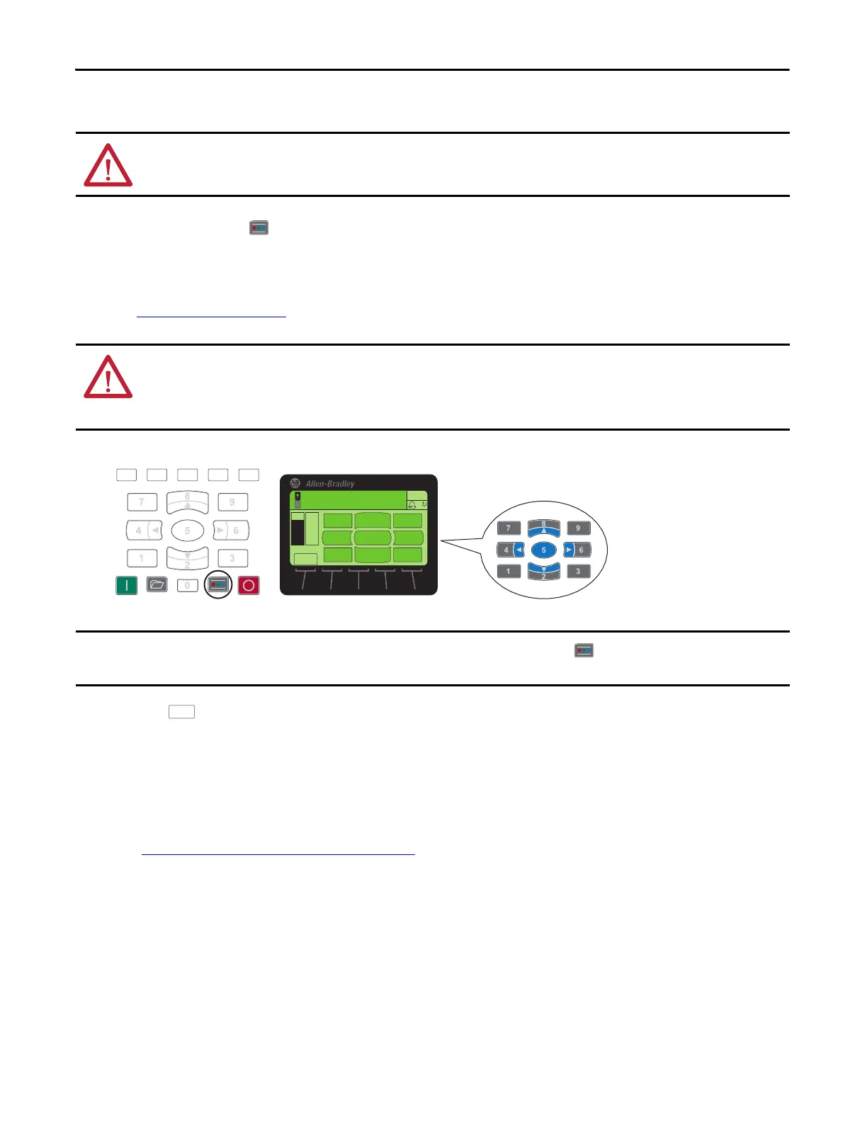
1. Press the Controls key on the keypad.
2. Use Jog to bump the motor shaft to verify direction.
If the motor shaft’s direction of rotation is NOT correct, shut power off and follow all safe practices to change motor
po
wer terminals U/T1 and V/T2 motor wire connections at the drive or at the motor.
See
Power Wiring on page 23.
3. Press the soft key to exit direction test.
Configuration Complete
The drive is able to start/stop from the HIM and has been successfully started up.
Proceed to
Step 4: Set Up Speed Reference and Start/Stop to complete your drive setup.
ATTENTION: This procedure causes movement of the motor shaft and of any connected equipment. To guard against personal
injury or damage to equipment, ensure that all guards are properly installed to help protect against contact with rotating parts.
ATTENTION: If changing the wires on U/T1 and V/T2 is not practical or desired, you can set parameter 40 [Reverse Motor Leads],
bit 4 to ‘1’. It is important to note, however, that parameter 40 [Reverse Motor Leads] resets to ‘0’ if parameters are reset to fact
ory
default. It is necessary to reset parameter 40 [Reverse Motor Leads] bit 4 to ‘1’ after resetting the parameters to default to prevent
personal injury or damage to the equipment.
ESC
REF
MANUAL
FBKREF
REMOVE
HIM
EDIT
REF
FWDREV
REF
JOG HELP
Control screen key function map
corresponds to navigation/number keys.
Stopped
0.000 Hz
AUTO
F
If the motor power terminals were changed, it is necessary to press the Controls key on the keypad and Jog to bump the
motor shaft to verify the direction change.

 Loading...


