28 Rockwell Automation Publication 750-QS001A-EN-P - March 2015
Reference Section
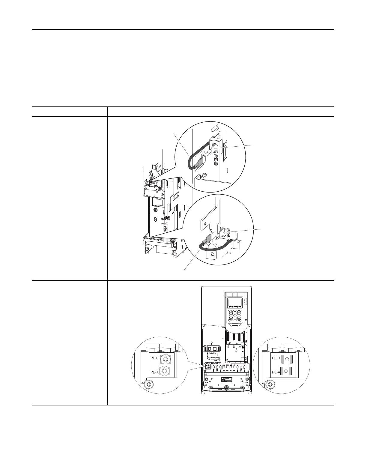
Power Jumper Locations
Wall/flange mount frames 1, 6, and 7 and floor mount frames 8…10 use jumper wires to complete an electrical connection
when installed.
Wall/flange mount frames 2…5 use jumper screws to complete an
electrical connection when installed.
Table 1 - Power Jumper Locations for Frames 1…10
Drive Jumper Locations
Frame 1
Spade Connectors
Frames 2…5
Screw Connectors
• Torque: 1.36 N•m (12.0 lb•in)
• Tool: 6.4 mm (0.25 in.) flat
or T15 Hexalobular
)
PE-A
PE-B
Disconnected
Connected
Disconnected
Connected
Disconnected
Connected
Frame 4 Shown

 Loading...


