Rockwell Automation Publication 750-QS001A-EN-P - March 2015 41
Reference Section
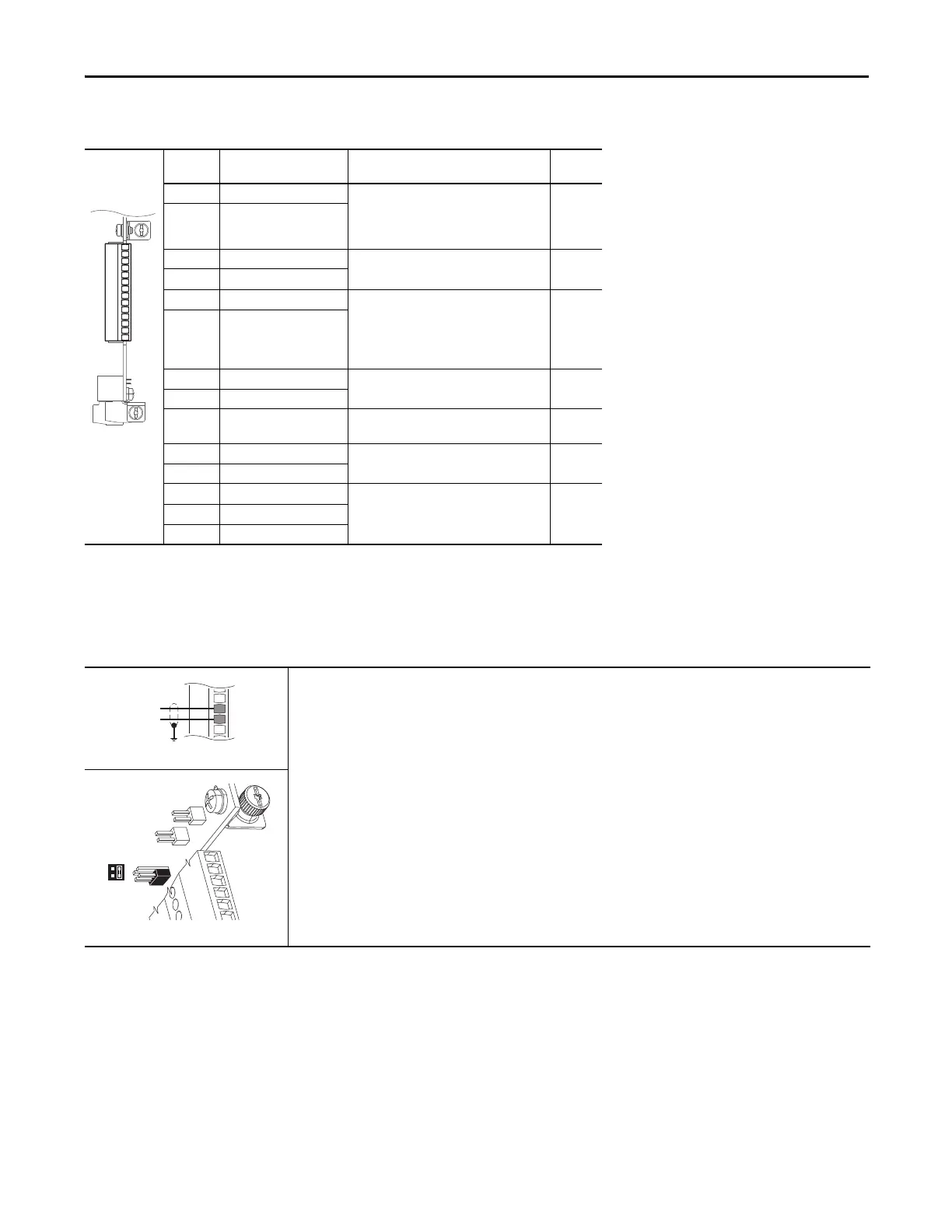
Table 12 - TB1 Terminal Designations
Terminal Name Description Related
Param
Ao0– Analog Out 0 (–) Bipolar, ±10V
(1)
, 11 bit & sign, 2 k ohm
minimum load.
4-20 mA
(1)
, 11 bit & sign, 400 ohm maximum
load.
(1) Mode is selected by parameter only.
270
Ao0+ Analog Out 0 (+)
10VC 10 Volt Common For (+) 10 Volt references.
2k ohm minimum.
+10V +10 Volt Reference
Ai0– Analog Input 0 (–) Isolated
(2)
, bipolar, differential, 11 bit & sign.
Voltage Mode:
(3)
±10V @ 88k ohm input
impedance.
Current Mode:
(3)
0-20 mA @ 93 ohm input
impedance
(2) Differential Isolation - External source must be maintained at less than 160V with respect to PE. Input provides high common mode
immunity.
(3) Mode is selected by jumper J4.
255
Ai0+ Analog Input 0 (+)
Ptc– Motor PTC (–) Motor protection device
(Positive Temperature Coefficient).
250
Ptc+ Motor PTC (+)
T0 Transistor Output 0 Open drain output, 48V DC, 250 mA
maximum
load
.
24VC 24 Volt Common Drive supplied logic input power.
150 mA maximum
+24V +24 Volt DC
Di C Digital Input Common 24V DC (30V DC Max.) - Opto isolated
High State: 20…24V DC
Low State: 0…5V DC
220
Di 1 Digital Input 1
Di 2 Digital Input 2
Ao0-
Ao0+
10VC
+10V
Ai0-
Ai0+
Ptc-
Ptc+
To0
24VC
+24V
Di C
Di 1
Di 2
Table 13 - 0…20 mA Analog Input - Unipolar Speed Reference
753 Main Control Board TB1
Set Direction Mode
Port 0: P308 [Direction Mode] =
0 “Unipolar”
Set Selection
Port 0: P545 [Spd Ref A Sel] = Port 0: P260 [Anlg In0 Value]
Adjust Scaling
Port 0: P261 [Anlg In0 Hi] = 20 mA
Port 0: P262 [Anlg In0 Lo] = 0 mA
Port 0: P547 [Spd Ref A AnlgHi] = 60 Hz
Port 0: P548 [Spd Ref A AnlgLo] = 0 Hz
View Results
Port 0: P260 [Anlg In0 Value]
Port 0: P592 [Selected Spd Ref]
Jumper set to current mode.

 Loading...


