Rockwell Automation Publication 750-PC108A-EN-P - April 2021 19
PowerFlex 755T Drives Configured to Order Program Product Information
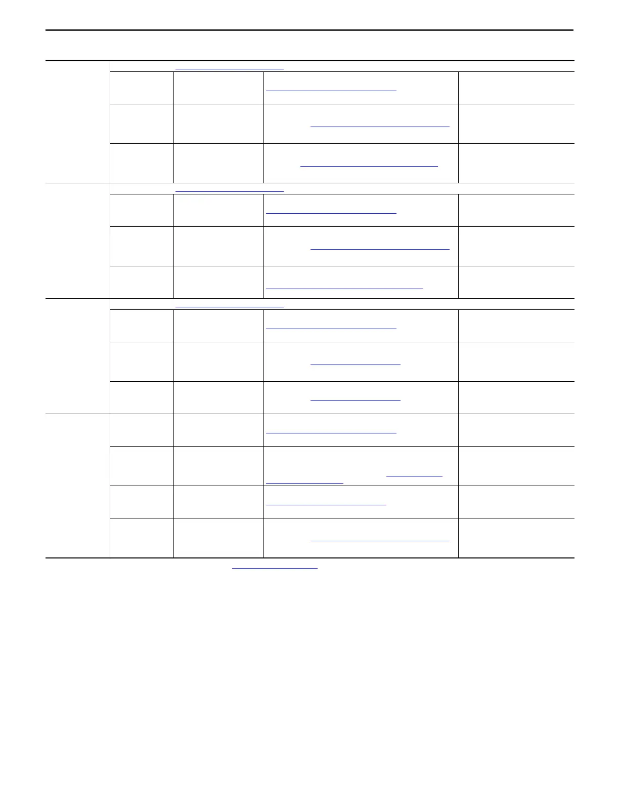
Configured input bay,
fuses, top entry
All connections in frame 9 Configured input bay, control-only
on page 18
PE ground bar Drive PE ground bar PE Ground Bar Splice Connection Hardware on page 38
• Connected to configured input bay PE
ground bar
• Must be connected to drive input bay PE
ground bar during installation
AC power input extruded
busbars
Customer AC power source Power cables with Barrel Lug to L-Bracket to Busbar Connections
on page 45
• The L-brackets are connected to the
busbar.
• The cable is provided by the customer, and
must be connected to the L-brackets
during installation.
AC power output busbars Drive AC power input busbar Flexibars. See Flexibar Flexible Busbar Connection Hardware
on page 39.
• Shipped in a box that comes with the
configured input bay
• Must be connected to both the configured
input bay and the drive input bay during
installation
Configured input bay,
fuses, bottom entry
All connections in frame 9 Configured input bay, control-only
on page 18
PE ground bar Drive PE ground bar PE Ground Bar Splice Connection Hardware on page 38
• Connected to configured input bay PE
ground bar
• Must be connected to drive input bay PE
ground bar during installation
AC power input busbars Customer AC power source Power cables with Barrel Lug to L-Bracket to Busbar Connections
on page 45
• The L-brackets are connected to the
busbar.
• The cable is provided by the customer, and
must be connected to the L-brackets
during installation.
AC power output busbars Drive AC power input busbars
Power cables with single bolt barrel lug connections provided standard. See
Barrel Lug to Drive Input Busbar Connection Hardware
on page 40.
• Inside the configured input bay
• Connected to the configured input bay
• Must be connected to the drive during
installation
Configured input bay,
circuit breaker, top or
bottom entry
All connections in frame 9 Configured input bay, control-only
on page 18
PE ground bar Drive PE ground bar PE Ground Bar Splice Connection Hardware on page 38
• Connected to configured input bay PE
ground bar
• Must be connected to drive input bay PE
ground bar during installation
AC power input terminals
on circuit breaker
Customer AC power source Power cables with Terminal Lug Connections
on page 46
• The terminal lugs are connected to the
circuit breaker.
• The cables are provided by the customer,
and must be connected to the terminal lugs
during installation.
AC power output
terminals on circuit
breaker
Drive AC power input busbar Power cables with Terminal Lug Connections
on page 46
• Inside the configured input bay
• Connected to the circuit breaker
• Must be connected to the drive input bay
during installation
Configured output bays,
top or bottom exit
PE ground bar Drive PE ground bar PE Ground Bar Splice Connection Hardware
on page 38
• Connected to configured output bay PE
ground bar
• Must be connected to drive power bay PE
ground bar during installation
Configured bay control
connectors in
configured output bay
Configured bay control connectors
in configured input bay
Each configured bay control connector in the configured input bay connects to
a configured bay control connector in the configured output bay. The
connection hardware for each of these connections is a bundle of 16 AWG
control cables, with connectors on both ends. See Configured Bay Control
Connection Hardware on page 41.
• Inside the drive bays
• Must be connected to the configured input
bay and configured output bay during
installation
AC power input busbar Drive AC power output busbar AC Busbar Splice Connection Hardware
on page 38
• Connected to configured output bay AC
power input busbar
• Must be connected to drive power bay
during installation
AC power output busbar Customer motor Power cables with Barrel Lug to L-Bracket to Busbar Connections
on page 45
• The L-brackets are connected to the
busbar.
• The cables are provided by customer, and
must be connected to the L-brackets
during installation.
(1) Not all grounding connections included. For grounding connections, see Grounding Requirements
on page 17.
Table 8 - Frame 9 Configured Bays - Bay to Bay, Bay to Customer Power Source, and Bay to Customer Motor Electrical Connections Made During Installation
(1)
 Loading...


