EasyManuals Logo

Allen-Bradley PowerFlex 755T Product Information, Original Instructions

Allen-Bradley PowerFlex 755T
48 pages
To Next Page IconTo Next Page
To Previous Page IconTo Previous Page
Page #31 background imageLoading...
Page #31 background image
Rockwell Automation Publication 750-PC108A-EN-P - April 2021 31
PowerFlex 755T Drives Configured to Order Program Product Information
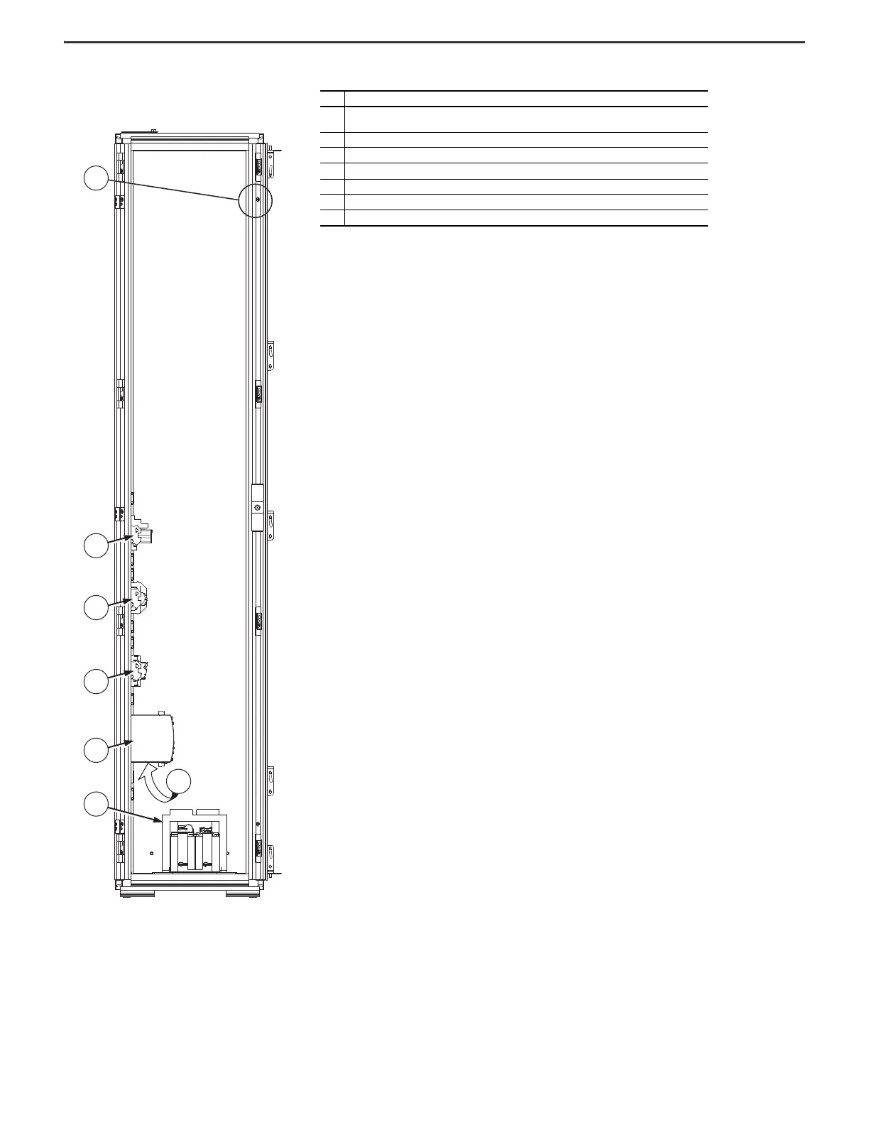
Figure 28 - Frame 9 Configured Input Bay Control-only: Internal
Components and Installation Connection Locations
Item Description
1
Configured bay control connectors for control connections to configured output bay (not visible in this
view, located behind bay frame). Connections must be made during installation.
2Control relays
3 Control terminal blocks
4Fuse blocks
5 Control power supply (24V DC)
6 Uninterruptible power supply, and battery (behind control power supply)
7 Control transformer
1
2
3
4
5
7
6

Table of Contents

Other manuals for Allen-Bradley PowerFlex 755T

Questions and Answers:

Question and Answer IconNeed help?

Do you have a question about the Allen-Bradley PowerFlex 755T and is the answer not in the manual?

Allen-Bradley PowerFlex 755T Specifications

General IconGeneral
BrandAllen-Bradley
ModelPowerFlex 755T
CategoryAdapter
LanguageEnglish

Related product manuals