Rockwell Automation Publication 750-PC108A-EN-P - April 2021 35
PowerFlex 755T Drives Configured to Order Program Product Information
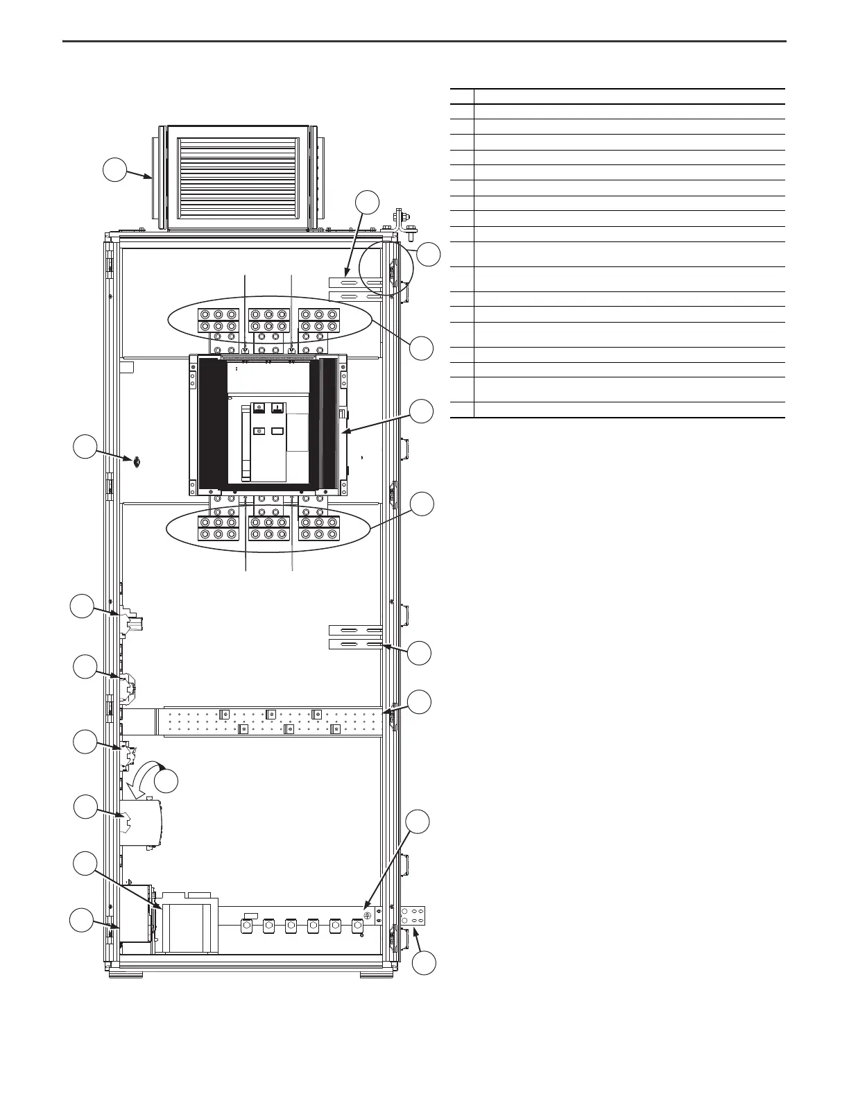
Figure 32 - Frame 9 Configured Input Bay with Circuit Breaker, Bottom Entry: Internal Components and Installation
Connection Locations
Item Description
1 Exhaust hood with internal air filter
2Thermostat
3 Control relay
4 Control terminal blocks
5Fuse blocks
6 Uninterruptible power supply (behind control power supply)
7 Control power supply (24V DC)
8 Control transformer
9 Battery
10
PE ground bar splice connection hardware. Ground splice connection to drive PE ground bar
must be made during installation.
11
PE ground bar with ground clamps included. Terminating point to chassis ground for
incoming AC line and shield. Ground connections must be made during installation.
12 Cable support bracket - support and guide customer AC line input power cables
13 Cable support brackets - support and guide power cables that connect to the drive input bay
14
Terminal lugs for customer AC line input power. Connections must be made during
installation.
15 AC line input protection circuit breaker
16 Terminal lugs to supply power to the drive input bay
17
Configured bay control connectors for control connection to configured output bay (not
visible in this view, located behind bay frame). Connections must be made during installation.
18 Cable support brackets - support and guide power cables that connect to the drive input bay
1
2
3
4
5
6
7
8
9
10
12
11
16
15
14
18
17
13

 Loading...


