2–2
Setting Up the SLC and PC Hardware
Publication
1747-10.4
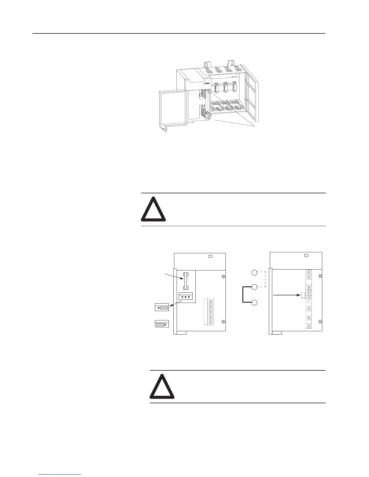
2. Fasten the power supply to the chassis.
Use these screws to fasten the
power supply to the chassis.
3. Make jumper selection for 120/240V ac on 1746-P1, 1746-P2,
and 1746-P4 Power Supplies.
Place the input voltage jumper to match the input voltage. This
does not apply to the 1746-P3 or 1746-P5, which do not have
jumpers.
!
ATTENTION: Set the input jumper before applying
power. Hazardous voltage is present on exposed pins
when power is applied; contact with the pin may cause
injury to personnel.
POWER
100/120 Volts
200/240 V
olts
Catalog Number
1746-P1 & P2
Fuse
85–132 V
AC
170–265 V
AC
Catalog Number
1746-P4
Jumper Selection
Jumper Selection
POWER
4. Wire power to power supply.
!
ATTENTION: Turn off incoming power before
connecting wires; failure to do so could cause injury
to personnel and/or equipment.

 Loading...


