2–3
Setting Up the SLC and PC Hardware
Publication
1747-10.4
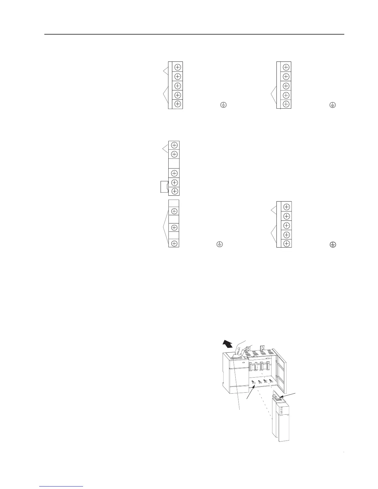
5. Connect incoming power, as shown in the following diagrams.
120/240V
ac
V ac NEUT
CHASSIS GROUND
dc NEUT
+ 24V dc
CHASSIS GROUND
JUMPER
170–265V ac
L2
NEUTRAL
L185–132/170–265
85–132V ac
CHASSIS GROUND
+125V dc
dc NEUT
CHASSIS GROUNDCHASSIS GROUND
PWR OUT COM
PWR OUT COM
PWR OUT +24V dc
PWR OUT +24V dc
PWR OUT +24V dc
PWR OUT COMMON
NOT USED
NOT USED
User
Power
1746-P1 and -P2
1746-P4 1746-P5
1746-P3
Incoming
Power
Incoming
Power
User
Power
Incoming
Power
User
Power
Incoming
Power
Make sure system power is off; then insert the processor into the
1746 chassis.
Important: SLC 500 Modular Processors must be inserted into the
left slot (slot 0), as shown below. Remove the
protective label after installing the processor.
Card Guide
Module Release
Protective Label
Install the Processor

 Loading...


