5–12
Using RS232-to-Ethernet
Channel-to-Channel Passthru
Publication
1747-10.4
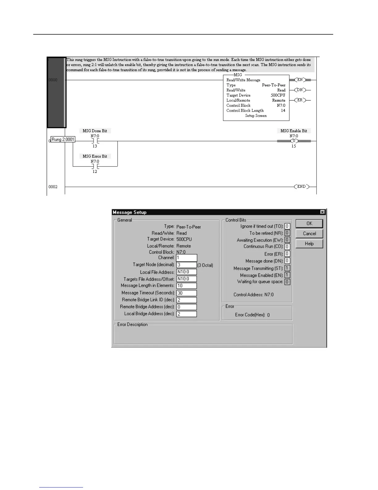
SLC 5/03 Ladder Logic
SLC 5/03 Message Setup
• Channel is set to one, the DH485 default.
• Target Node is the address in the SLC 5/05 #1 routing table
where the IP address for SLC 5/05 #2 is stored.
• The Message Timeout must be at least as long as the SLC
5/05 timeout for Ethernet connection. The SLC 5/05 default
timeout is 23 seconds.
• The Remote Bridge Link ID is the Link ID of Channel 1 of
the SLC 5/05 #1 bridge.
• The Remote Bridge Address is always zero to point to the IP
address for the bridge’s (SLC 5/05 #1) Ethernet channel.
• The Local Bridge Address is the Channel 0 DH485 node
address of the SLC 5/05 #1 bridge.

 Loading...


