5–18
Using RS232-to-Ethernet
Channel-to-Channel Passthru
Publication
1747-10.4
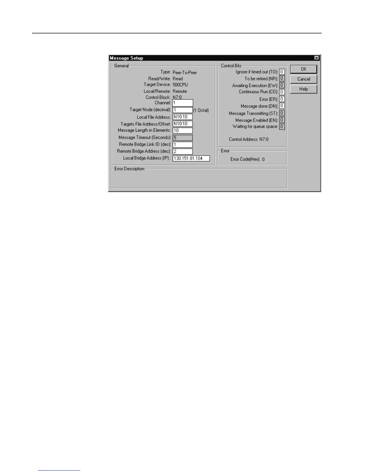
SLC 5/05 #2 Message Setup
• Channel is set to one for Ethernet.
• Target Node is the DH485 node address of the SLC 5/03
destination processor.
• Message Timeout for any Ethernet MSG cannot be modified in
the Ethernet Message Setup dialog box. It is assigned by the
processor, and is determined by adding the Channel 1 MSG
Connection Timeout to the MSG Reply Timeout, then adding 5
seconds. This value can be modified by changing one or both of
the timeout values in the Channel 1 channel configuration screen.
The modified message timeout applies to all MSG instructions.
• The Remote Bridge Link ID is the Link ID of Channel 0 of the
SLC 5/05 #1 bridge.
• The Remote Bridge Address is the DH485 address for Channel
0 of SLC 5/05 #1.
• The Local Bridge Address is the IP address of the SLC 5/05 #1
bridge.

 Loading...


