12 SLC 500™ RTD/Resistance Input Module
Publication 1746-IN012B-EN-P - May 2001
There are several ways to insure that the lead values match as closely as possible.
They are as follows:
• Keep lead resistance as small as possible and less than 25Ω.
• Use quality cable that has a small tolerance impedance rating.
• Use a heavy-gauge lead wire which has less resistance per foot.
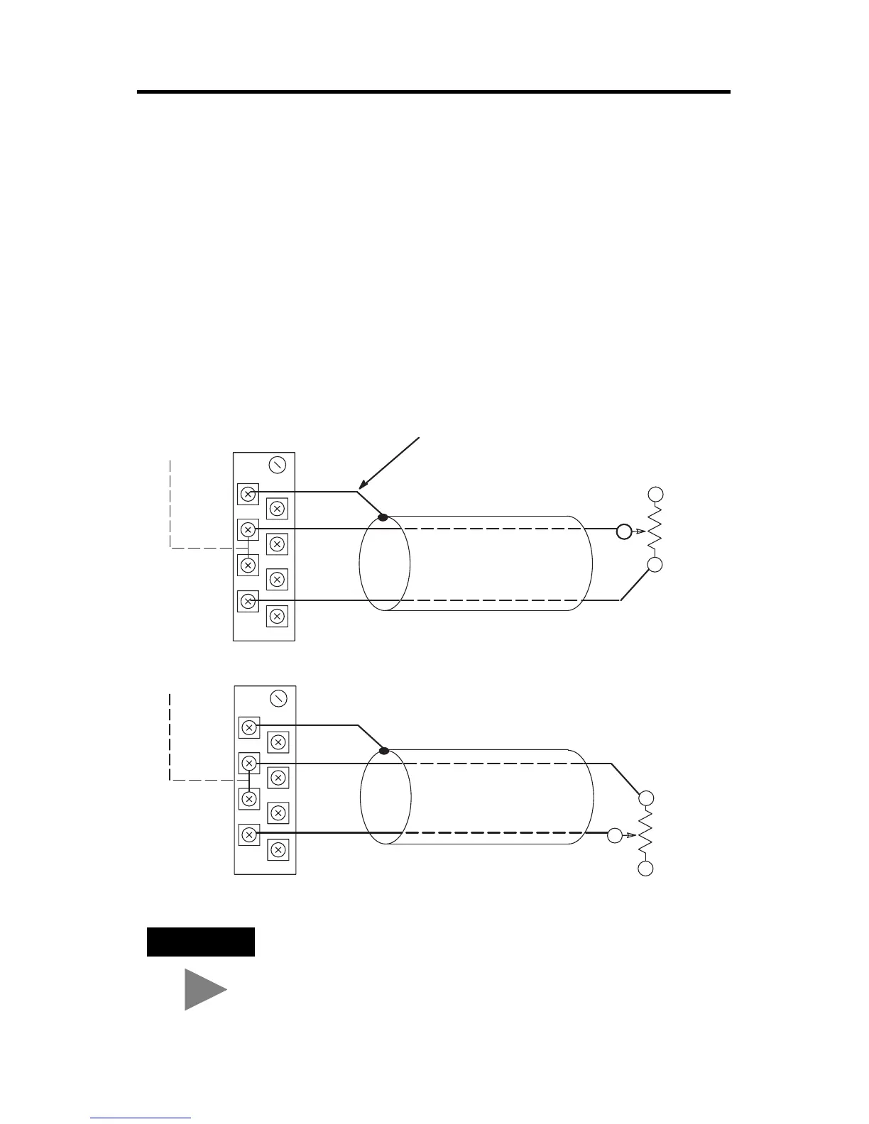
Wiring Resistance Devices (Potentiometers) to the NR4 Module
Potentiometer wiring requires the same type of cable as that for the RTD described
on page 9. Potentiometers can be connected to the RTD module as a 2-wire
interconnection or a 3-wire interconnection as shown on the following pages.
TIP
Potentiometer wiper arm can be connected to either the RTD
or Return terminal, depending on whether you want
increasing or decreasing resistance.
Cable Shield
Potentiometer
RTD
Return
Belden #9501 Shielded Cable
Add Jumper
Shield
CH 0 RTD
CH 0 Sense
CH 0 Return
Potentiometer
RTD
Return
Belden #9501 Shielded Cable
Add Jumper
Shield
CH 0 RTD
CH 0 Sense
CH 0 Return

 Loading...


