4 SLC 500™ RTD/Resistance Input Module
Publication 1746-IN012B-EN-P - May 2001
Required Tools and Equipment
Have the following tools and equipment ready
• medium blade screwdriver
• medium cross-head screwdriver
• RTD module (1746-NR4)
• RTD sensor or resistance input
• appropriate cable (if needed)
• programming equipment
INPUT
CHL
1
SHIELD
SHIELD
CHL
0
RTD
SHIELD
MODULE STA TUS
0
1
2
3
CHANNEL
STATUS
RTD/resistance
RT D
CHL
0
SENSE
CHL
1
SENSE
CHL
0
RETRN
CHL
1
RETRN
SHIELD
CHL
3
CHL
2
RTD
RT D
CHL
2
SENSE
CHL
3
SENSE
CHL
2
RETRN
CHL
3
RETRN
SHIELD
SHIELD
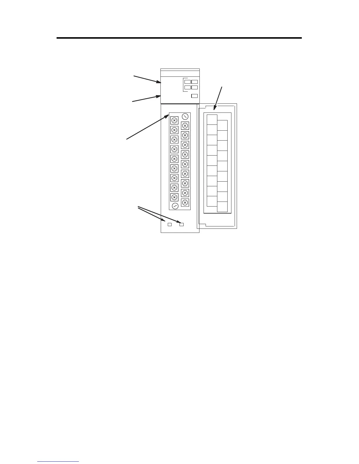
Door Label
Channel Status LEDs
(Green)
Module Status LED
(Green)
Removable Terminal
Block
Cable Tie Slots

 Loading...


