SLC 500™ RTD/Resistance Input Module 15
Publication 1746-IN012B-EN-P - May 2001
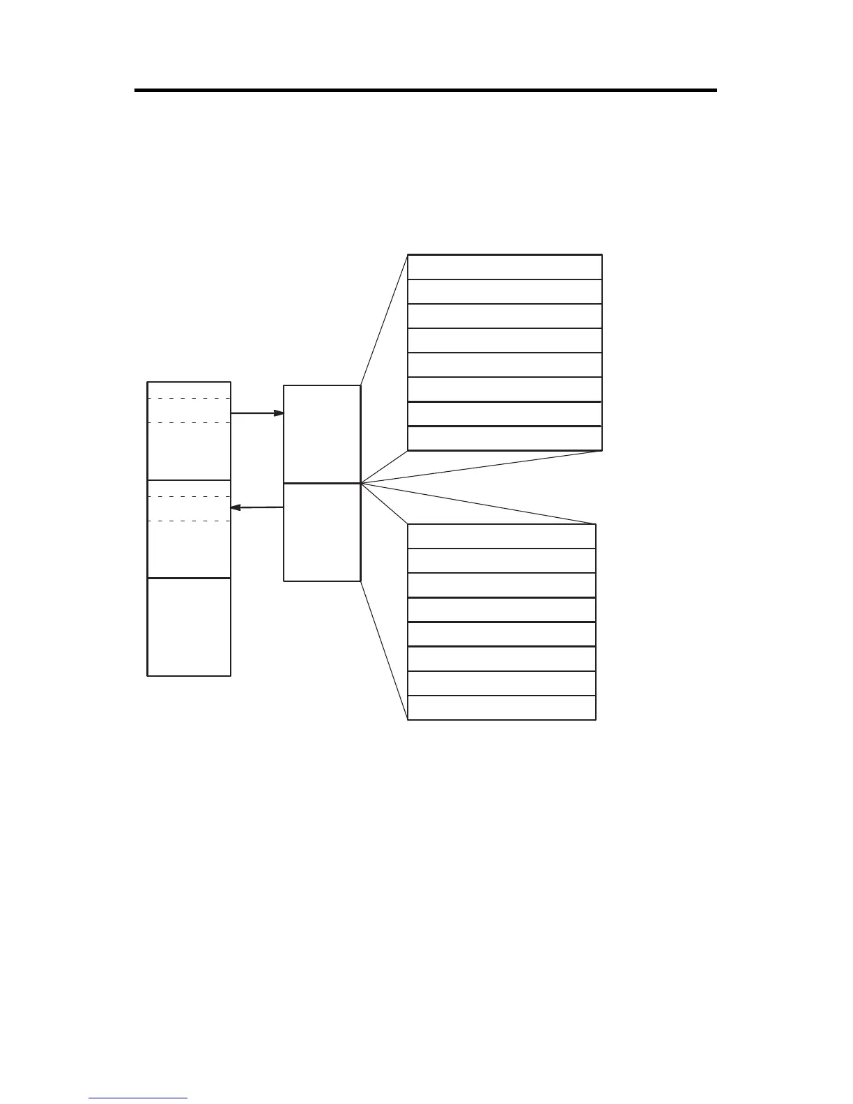
Module Addressing
The following memory map of shows you how the output and input image tables
are defined for the RTD module.
SLC 5/0X Data
Files
Slot e
Slot e
Output Image
Input Image
Output
Scan
Input
Scan
RTD
Module
Image Table
Output Image
8 Words
Input Image
8 Words
(Class 1)
Bit 15
Bit 15 Bit 0
Bit 0
Channel 0 Configuration Word
Channel 1 Configuration Word
Channel 2 Configuration Word
Channel 3 Configuration Word
User-set Lower Scale Limit Range 0
User-set Upper Scale Limit Range 0
User-set Lower Scale Limit Range 1
User-set Upper Scale Limit Range 1
Word 0
Word 1
Word 2
Word 3
Word 4
Word 5
Word 6
Word 7
Address
Address
Word 0
Word 1
Word 2
Word 3
Word 4
Word 5
Word 6
Word 7
Channel 0 Data Word
Channel 1 Data Word
Channel 2 Data Word
Channel 3 Data Word
Channel 0 Status Word
Channel 1 Status Word
Channel 2 Status Word
Channel 3 Status Word
O:e.0
O:e.1
O:e.2
O:e.3
O:e.4
O:e.5
O:e.6
O:e.7
I:e.0
I:e.1
I:e.2
I:e.3
I:e.4
I:e.5
I:e.6
I:e.7

 Loading...


