SLC 500™ RTD/Resistance Input Module 7
Publication 1746-IN012B-EN-P - May 2001
Module Installation and Removal
When installing the module in a chassis, it is not necessary to remove the terminal
block from the module.
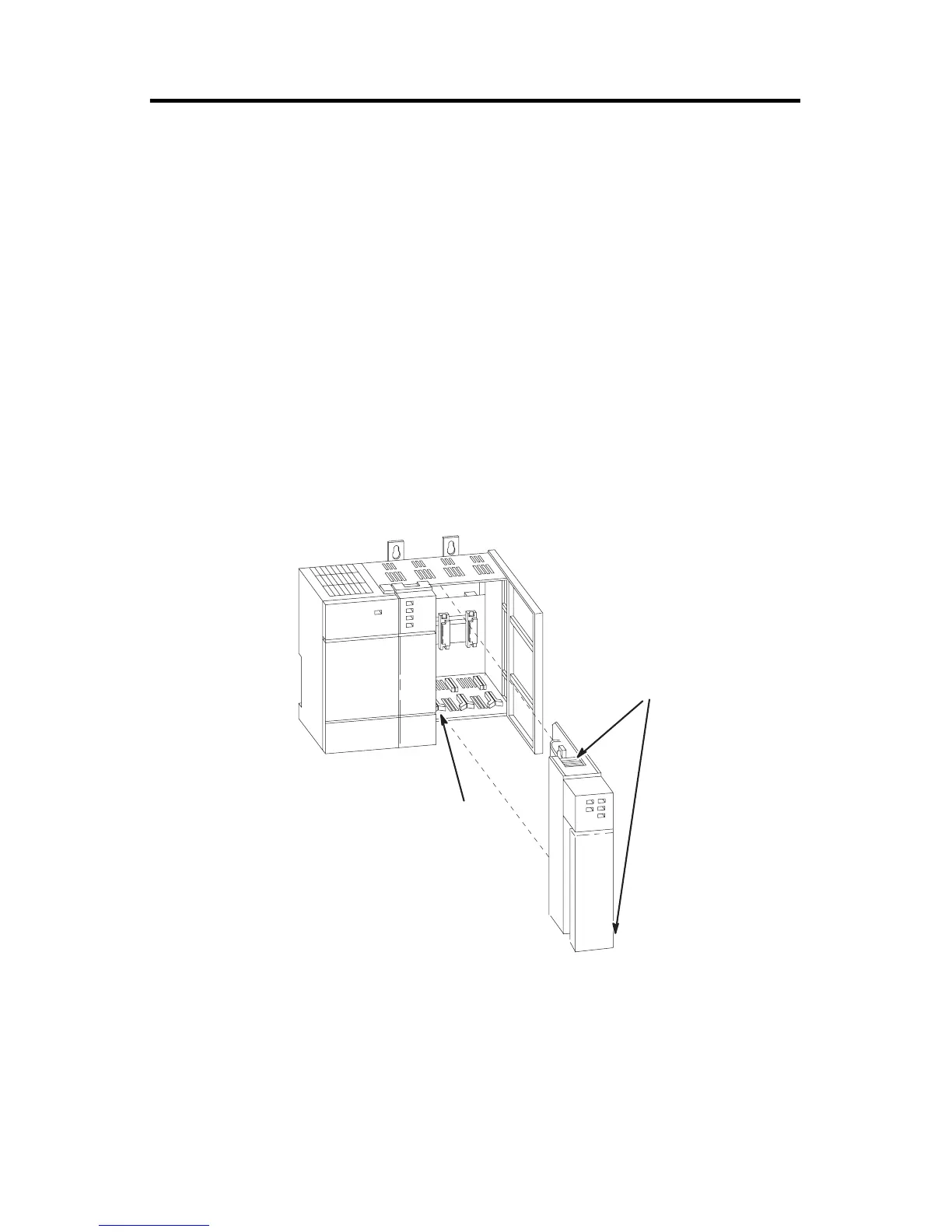
Module Installation Procedure
1. Align the circuit board of the RTD module with the card guides located at
the top and bottom of the chassis.
2. Slide the module into the chassis until both top and bottom retaining clips
are secured. Apply firm even pressure on the module to attach it to its
backplane connector. Never force the module into the slot.
3. Cover all unused slots with the Card Slot Filler, Catalog Number 1746-N2.
Module Removal Procedure
1. Press the releases at the top and bottom of the module and slide the module
out of the chassis slot.
2. Cover all unused slots with the Card Slot Filler, Catalog Number 1746-N2.
Top and Bottom Module Release(s)
Card Guide

 Loading...


