8 SLC 500™ RTD/Resistance Input Module
Publication 1746-IN012B-EN-P - May 2001
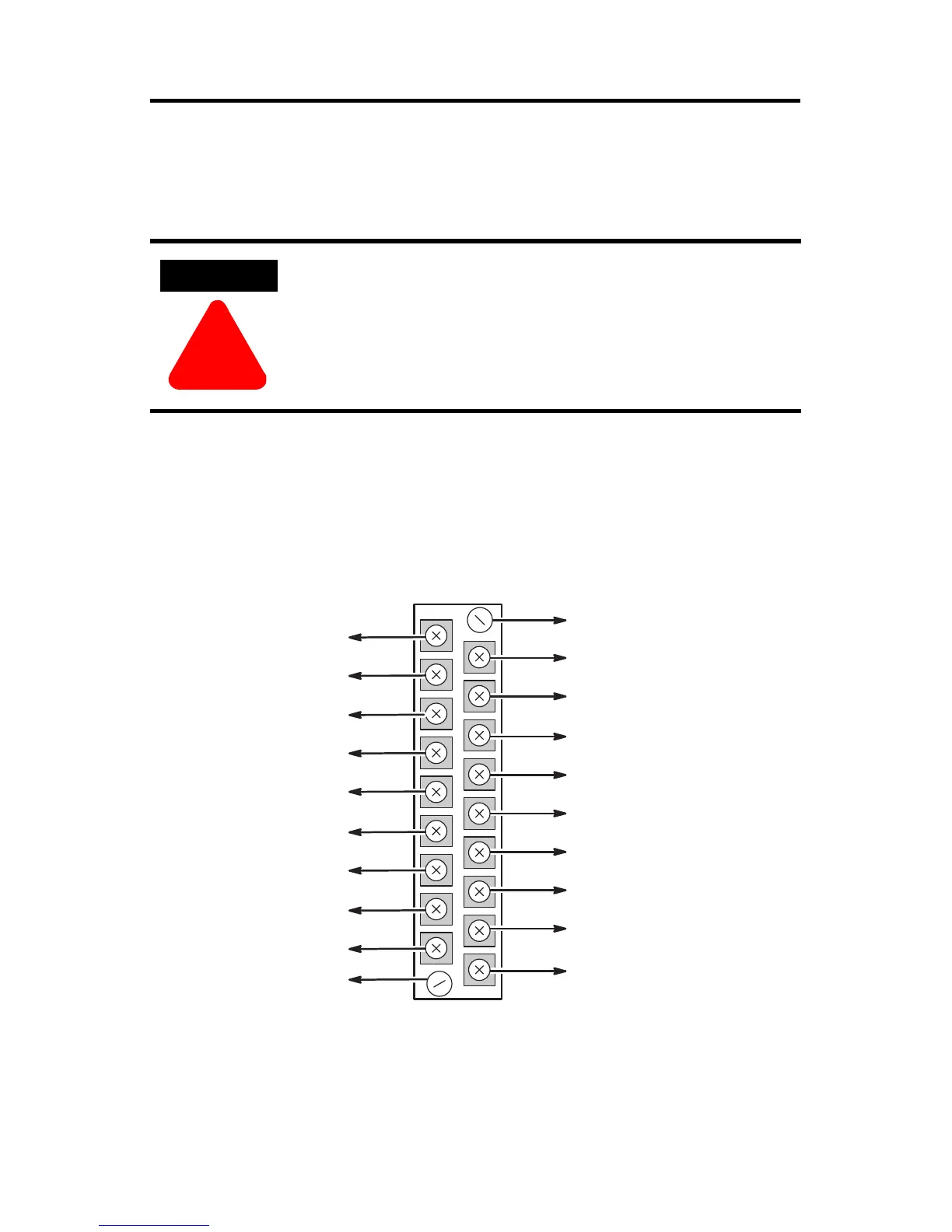
Terminal Block Wiring and Removal
The RTD module contains an 18-position, removable terminal block. The terminal
pin-out is shown below.
Terminal Wiring
Terminal screws accept a maximum of two #14 AWG (2 mm
2
) wires. Tighten
terminal screws only tight enough to immobilize wires. Maximum torque on
terminal screws is 0.7 to 0.9 Nm (6 to 8 in-lb.).
ATTENTION
!
Disconnect power to the SLC before attempting to install,
remove, or wire the removable terminal wiring block.
To avoid cracking the removable terminal block, alternate the
removal of the terminal block release screws.
Terminal Block Spare Part
Catalog Number 1746-RT25G
Shield
Channel 0 RTD
Channel 0 Sense
Channel 0 Return
Shield
Channel 2 RTD
Channel 2 Sense
Channel 2 Return
Shield
Release Screw Max Torque
= 0.7 - 0.9 Nm (6 - 8 in-lbs)
Release Screw Max Torque =
0.7 - 0.9 Nm (6 - 8 in-lbs)
Shield
Channel 1 RTD
Channel 1 Sense
Channel 1 Return
Shield
Channel 3 RTD
Channel 3 Sense
Channel 3 Return
Shield

 Loading...


