SLC 500™ RTD/Resistance Input Module 17
Publication 1746-IN012B-EN-P - May 2001
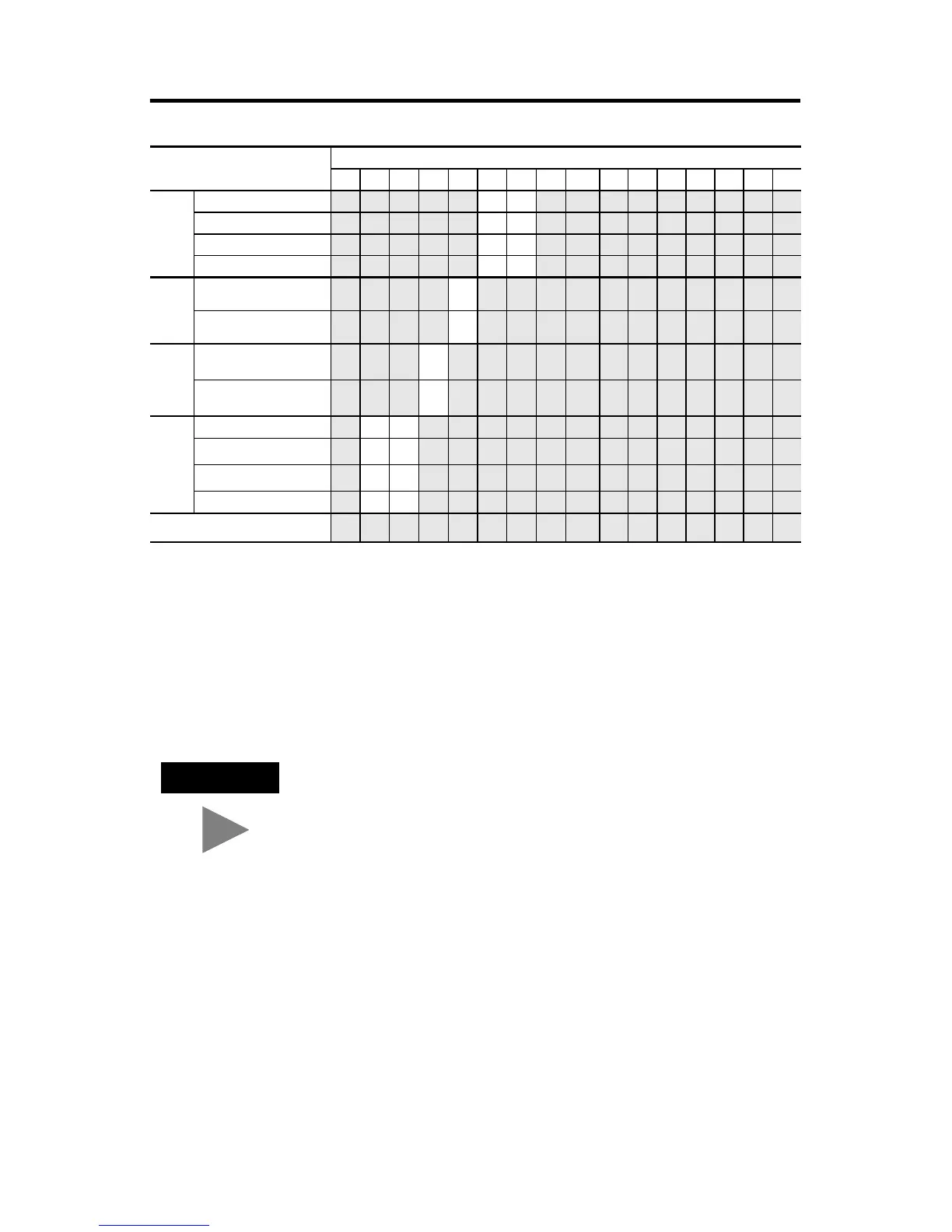
Filter
Frequency
10 Hz 00
50 Hz 01
60 Hz 10
250Hz 11
Enable
Channel
Enable 1
Disable 0
Excitation
Current
2.0 mA 0
0.5 mA 1
Scaling
Default 00
User-set (Range 0)
(6)
01
User-set (Range 1)
(6)
10
Invalid 11
Unused 0
(1) Actual value at 0°C is 9.042Ω per SAMA standard RC21-4-1966.
(2) Actual value at 0°C is 100Ω per DIN standard.
(3) Values are in 0.1 degree/step or 0.1Ω/step for all resistance input types, except 150Ω. For the 150Ω resistance type, the
values are in 0.01Ω/step.
(4) Values are in 1 degree/step or 1Ω/step for all resistance input types, except 150Ω. For the 150Ω resistance input type, the
values are in 0.1Ω/step.
(5) This bit is ignored when a resistance device is selected.
(6) Applies to proportional counts data format selected using bits 4 and 5.
TIP
Ensure that unused bit 15 is always set to zero.
To Select
Make these bit settings
15 14 13 12 11 10 9 8 7 6 5 4 3 2 1 0

 Loading...


