12 Rockwell Automation Publication 1783-IN016B-EN-P - March 2019
Stratix 5700 Ethernet Managed Switches
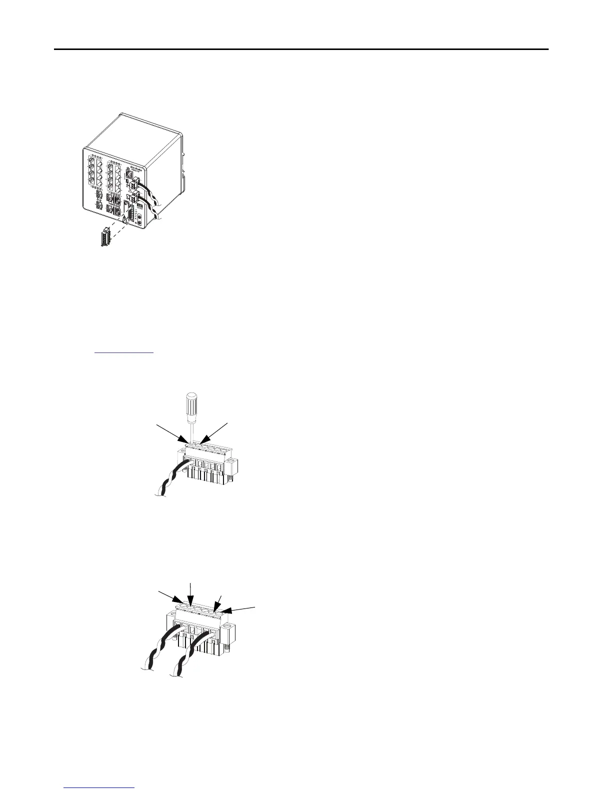
To wire the switch to an external alarm device, follow these steps.
1. Loosen the captive screws that hold the alarm relay connector on the switch, and remove the connector from the switch chassis.
2. Measure two strands of twisted-pair wire (18…20 AWG) long enough to connect to the external alarm device.
Choose between creating an external alarm input or output circuit.
3. Use a wire stripper to remove the casing from both ends of each wire to 6.3 mm (0.25 in.) ± 0.5 mm (0.02 in.).
Do not strip more than 6.8 mm (0.27 in.) of insulation from the wires. Stripping more than the recommended amount of wire can leave
exposed wire from the alarm relay connector after installation.
4. Insert the exposed wires for the external alarm device into the connections that are based on an alarm input or output circuit setup.
See
Table on page 11.
5. Use a ratcheting torque flathead screwdriver to torque the captive screw of the alarm relay connector to 0.23 N•m (2.0 in•lb).
Do not exceed the recommended torque.
6. Repeat the preceding procedure to insert the input and output wires of one more external alarm device into the alarm relay connector.
The following figure shows the completed wiring for two external alarm devices. The first alarm device circuit is wired as an alarm relay
input circuit—the IN1 and REF connections complete the circuit. The second alarm device circuit is wired as an alarm relay output circuit
by using the normally open side of the form C relay contacts. The NO and COM connections complete the circuit.
32288-M
IN1 - External Device Connection 1
REF - External Device Connection 2
IN1—External Device Connection 1
REF—External Device Connection 2
COM—Wired Connection
NO—Wired Connection

 Loading...


