14 Rockwell Automation Publication 1783-IN016B-EN-P - March 2019
Stratix 5700 Ethernet Managed Switches
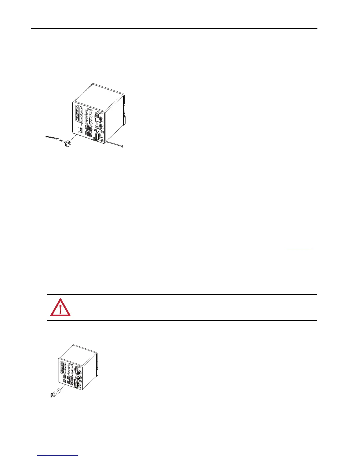
Install the PoE Power Connector on the Switch
This procedure applies only to switches with PoE ports.
1. Insert the power connector into the DC input terminal block on the switch front panel.
2. Use a screwdriver to tighten the captive screws on the sides of the power connector.
Install or Remove an SFP Module
On switch catalog numbers that support communication over fiber-optic cable, sfp modules are inserted into SFP module slots on the front of the
switch. These field-replaceable modules provide the uplink optical interfaces, send (TX) and receive (RX).
You can use any combination of compatible SFP modules:
• Each SFP module must be of the same type as the SFP module on the other end of the cable. The cable must not exceed the stipulated cable
length for reliable communications.
• Once you install SFP modules in the switch, be aware that the overall temperature rating of the combined modules (switch and SFP
modules) is limited to the lowest maximum temperature rating and the highest minimum temperature rating.
• For cable length and temperature specifications, see the Stratix Ethernet Device Specifications Technical Data, publication
1783-TD001.
To insert or remove an SFP module into an SFP slot, follow these steps.
1. Attach an ESD-preventive wriststrap to your wrist and to a grounded bare metal surface.
2. To install and SFP module, do the following.
a. Grasp both sides of the SFP module and align the module sideways in front of the slot opening.
b. Insert the SFP module into the slot as shown in the following figure until you feel the connector on the module snap into place in the
rear of the slot.
c. Remove the dust plugs from the SFP module optical ports, store them for later use.
ATTENTION: If the SFP module cannot be fully inserted, stop! Do not force the module into the slot. Rotate the SFP module 180° and try again.
PoE Input Pwr
48VDC, 1.2A

 Loading...


