18 Rockwell Automation Publication 1783-IN016B-EN-P - March 2019
Stratix 5700 Ethernet Managed Switches
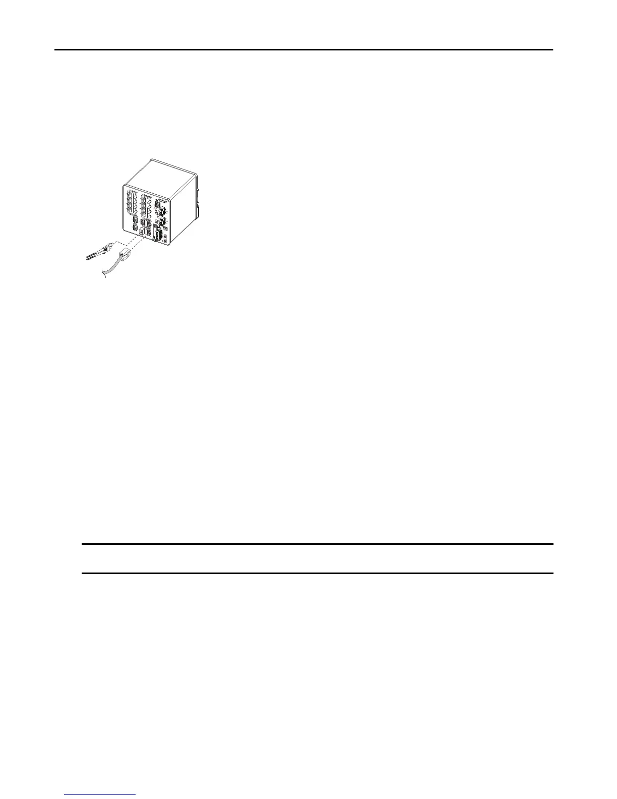
Connect to a Dual-purpose Port
A dual-purpose port is one port with two interfaces, one for an RJ45 cable and another for an approved SFP module. Only one interface can be
active at a time. If both interfaces are connected, the SFP module has priority.
To connect to a dual-purpose port, follow these steps.
1. Connect an RJ45 connector or install an SFP module into the SFP module slot, and connect a cable to the SFP module.
2. Connect the other end of the cable to the other device.
By default, the switch detects whether an RJ45 connector or SFP module is connected to a dual-purpose port and configures the port
accordingly. You can change this setting and configure the port to recognize only an RJ45 connector or only an SFP module by using the
media type interface configuration command.
Confirm Installation
To confirm the installation, power on the switch, and verify that the switch powers up. The time that is required for the switch to start up is directly
related to your switch configuration. Start time is negatively affected by such things as the following:
• Spanning Tree Learning mode
• Number of files or images in onboard memory
To test the switch, follow these steps.
1. Apply power to the switch.
If the switch is directly connected to a DC power source, locate the circuit breaker on the panel board that services the DC circuit, and
switch the circuit breaker to the On position.
2. Verify the start-up sequence.
When you power on the switch, it begins a start-up routine. The Setup status indicator blinks green as the IOS software image loads. If the
routine fails, the Setup status indicator turns red.
3. After successfully running this test, do the following:
a. Turn off power to the switch.
b. Disconnect the cables.
c. Decide where you want to install the switch
Remove Power from a Switch with PoE
Switches with PoE capability in the following configuration require special instructions to disconnect power:
• The switches are connected to the same power supply
• The PoE ports on both switches are connected to each other via Ethernet cables
If you use the above configuration, you must disconnect both DC+ and DC- connections to power down an individual switch.
IMPORTANT Start-up failures are usually fatal to the switch. Contact your Rockwell Automation representative immediately if your switch does not complete
the start sequence successfully.
32296-M

 Loading...


