14 Rockwell Automation Publication 1783-IN013B-EN-P - December 2019
Stratix 5800 Ethernet Managed Switches
Connect to 10/100/1000 Ports
The 10/100/1000 ports automatically configure themselves to operate at the speed of attached devices. If the attached ports do not support
autonegotiation, you can explicitly set the speed and duplex parameters. Connected devices that do not autonegotiate or that have speed and duplex
parameters that are manually set can reduce performance or result in no connection.
To maximize performance, choose one of these methods for configuring the Ethernet ports:
• Let the ports autonegotiate both speed and duplex.
• Set the port speed and duplex parameters on both ends of the connection.
To connect to 10Base-T, 100BASE-TX or 1000BASE-T devices, follow these steps.
1. When connecting to workstations, servers, or routers, connect a straight-through cable to an RJ45 connector on the front panel. When
connecting to 1000BASE-T-compatible devices, use a twisted four-pair, Category 5, or higher cable.
2. Connect the other end of the cable to an RJ45 connector on the other device.
The port status indicator turns on when both the switch and the connected device have established a connection. The port status indicator is amber
while Spanning Tree Protocol (STP) discovers the topology and searches for loops. This process can take up to 30 seconds, and then the port status
indicator turns green.
Connect to SFP Modules
If you installed an SFP module, follow these steps to connect a fiber-optic cable to an SFP module.
1. Remove the rubber plugs from the module port and fiber-optic cable, and store them for future use.
2. Insert one end of the fiber-optic cable into the SFP module port.
3. Insert the other cable end into a fiber-optic receptacle on a target device.
Confirm Installation
To confirm the installation, power on the switch, and verify that the switch powers up.
1. Apply power to the switch.
If the switch is directly connected to a DC power source, switch the circuit breaker to the ON position.
2. Verify the startup process.
The Setup status indicator blinks green as the IOS software image loads. If the routine fails, the Setup status indicator turns red.
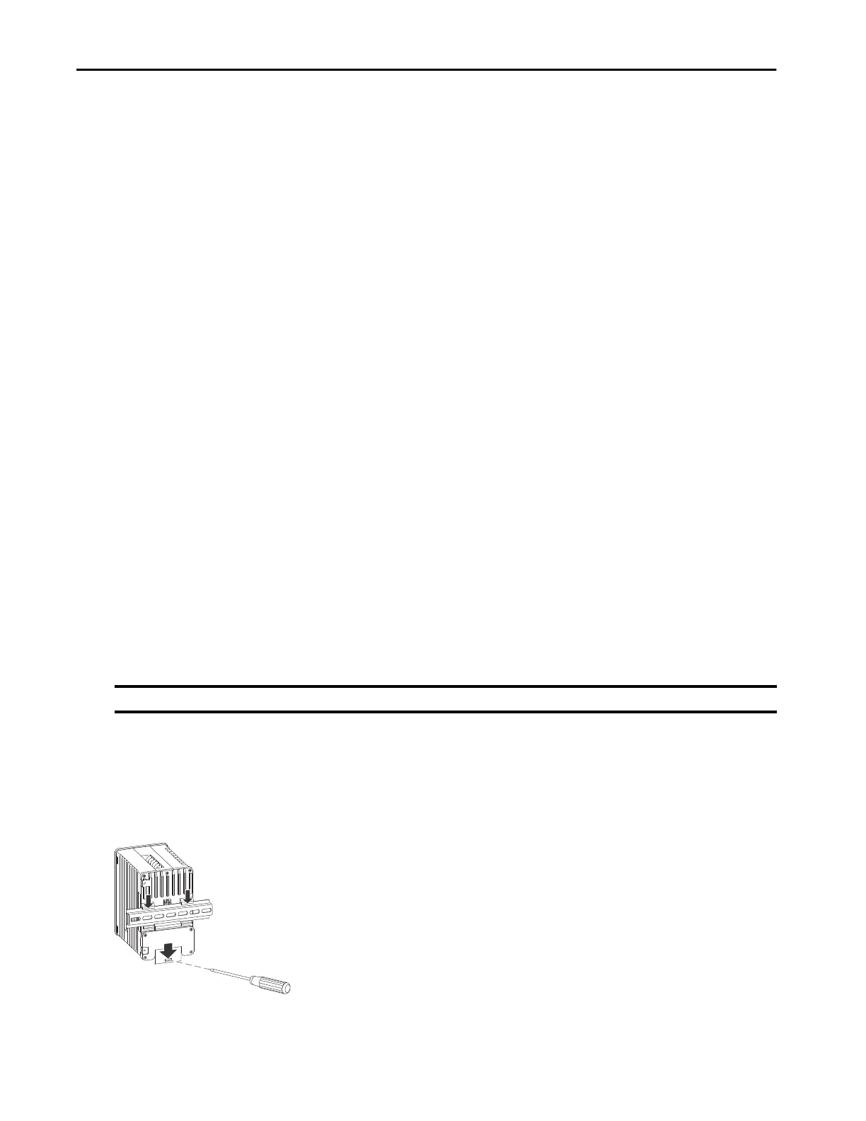
Remove the Switch from the DIN Rail
To remove the switch from a DIN rail, follow these steps.
1. Remove power from the switch and disconnect all cables and connectors from the front panel of the switch.
2. Insert a tool, such as a screwdriver, in the slot at the bottom of the spring-loaded latch and use it to release the latch from the rail.
3. Pull the bottom of the switch away from the DIN rail and lift the hooks off the top of the DIN rail.
4. Remove the switch from the DIN rail.
IMPORTANT Startup failures are fatal to the switch. If your switch does not complete the start sequence, contact Rockwell Automation.

 Loading...


