36 M411429
Section 3 Troubleshooting
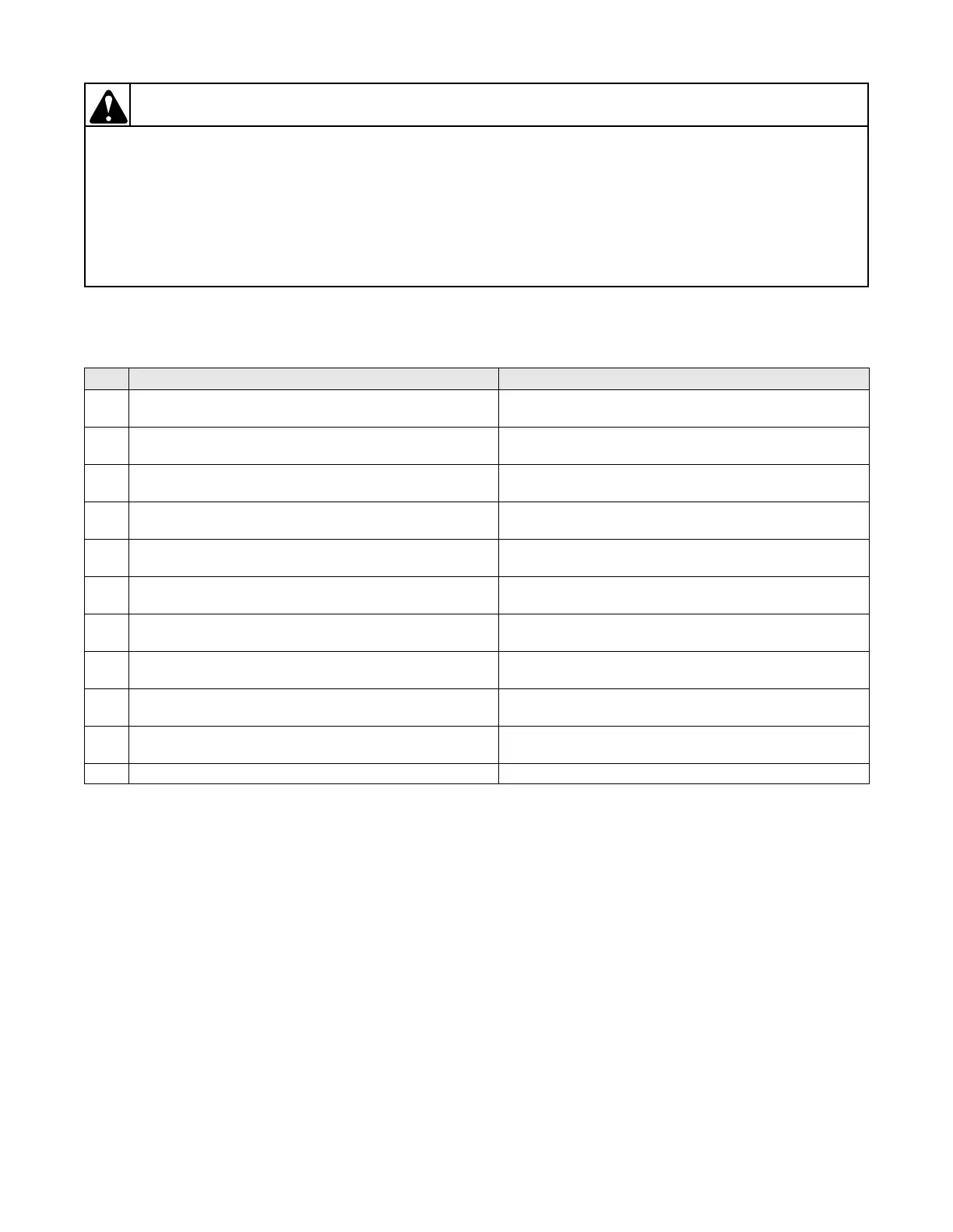
To reduce the risk of electric shock, fire, explosion, serious injury or death:
• Disconnect electric power to the tumbler before servicing.
• Close gas shut-off valve to gas tumbler before servicing.
• Close steam valve to steam tumbler before servicing.
• Never start the tumbler with any guards/panels removed.
• Whenever ground wires are removed during servicing, these ground wires must be
reconnected to ensure that the tumbler is properly grounded.
W002
WARNING
© Copyright, Alliance Laundry Systems LLC – DO NOT COPY or TRANSMIT
39. OM MODELS: NO FAN MOTOR ROTATION WITH CYCLE SELECTED AND START PRESSED
208-240 Volt/60 Hertz/3 Phase and 480 Volt/60 Hertz/3 Phase CE Reversing Models
208-240 Volt/60 Hertz/3 Phase and 460-480 Volt/60 Hertz/3 Phase CG Reversing and CSH Models
Step Problem If No, then
1 Is there voltage across the primary of the transformer?
If yes, continue to next step.
Correct wiring to transformer. Check fuses.
2 Is there 24 VAC across terminals 2 & 3 of the transformer
secondary? If yes, continue to next step.
Replace transformer.
3 Is there voltage to the COM of the door switch?
If yes, continue to next step.
Correct wiring to door switch. Check fuse.
4 Is there voltage to the N.O. terminal of the door switch?
If yes, continue to next step.
Check door switch and switch rod for proper operation.
Replace if necessary.
5 Is there voltage to H2-8 of micro control? If yes, continue
to next step.
Correct wiring between micro control and door switch.
6 Is there voltage to H2-7 of micro control? If yes, continue
to next step.
Replace micro control.
7 Is there voltage across the coil of the M contactor? If yes,
continue to next step.
Correct the wiring to the M contactor.
8 Is there voltage to L1, L2 and L3 of the M contactor?
If yes, continue to next step.
Correct wiring between M contactor and supply voltage.
9 Is there voltage toT1, T2 and T3 of the M contactor?
If yes, continue to next step.
Replace M contactor.
10 Is there voltage across L1, L2 and L3 of the motor?
If yes, continue to next step.
Correct wiring between motor and M contactor.
11 Unit operational.