AT-8000 Series Fast Ethernet Switches Installation Guide
37
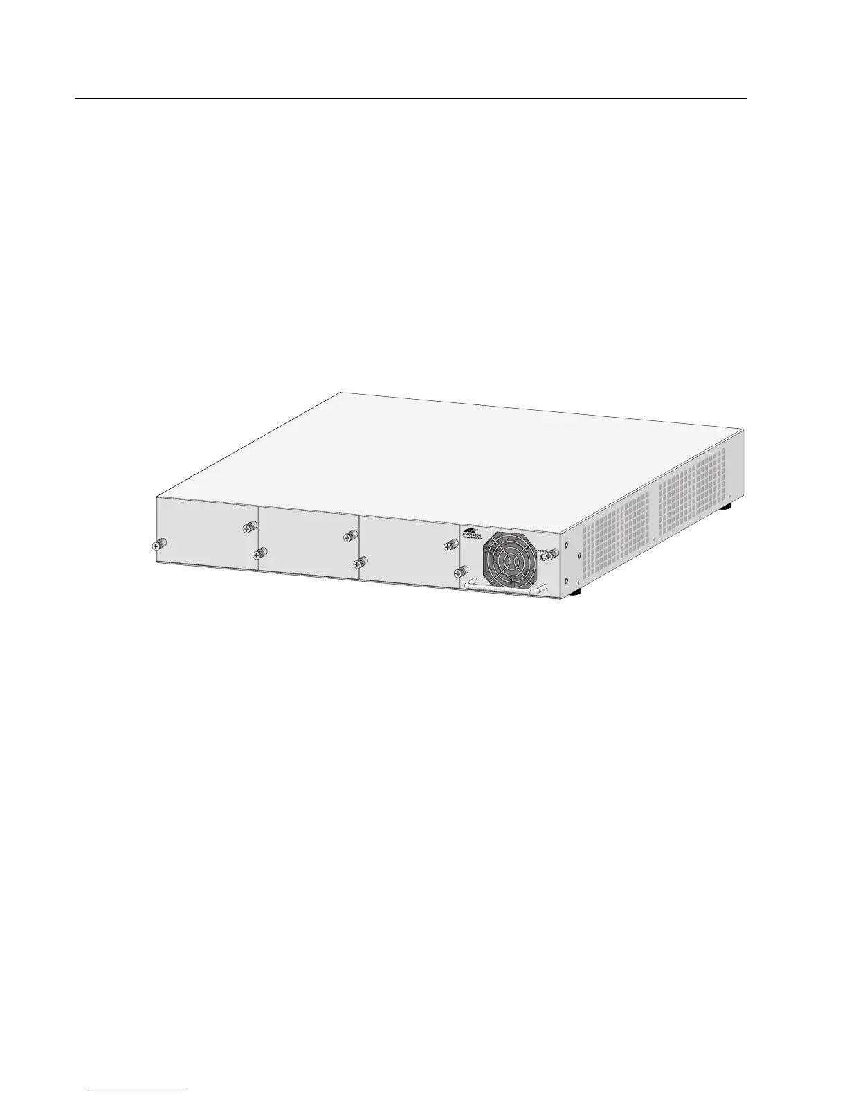
RPS Connector
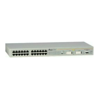
The RPS connector on the AT-8024M, AT-8016F/xx, and AT-8088/xx
switches is described below.
The RPS connector on the back panel of the switch connects to the
optional AT-RPS3004 redundant power supply unit, shown in Figure 13.
The unit can provide power to the switch in the event the switch’s
internal power supply should fail.
The AT-RPS3004 redundant external power supply comes with one pre-
installed AT-PWR3004 Power Module and has three empty slots for
additional power modules. Each power module can support one switch,
making the AT-RPS3004 unit capable of supporting up to four switches
simultaneously.
Figure 13. AT-RPS3004 Redundant Power Supply Unit
 Loading...