Technical Specifications
88
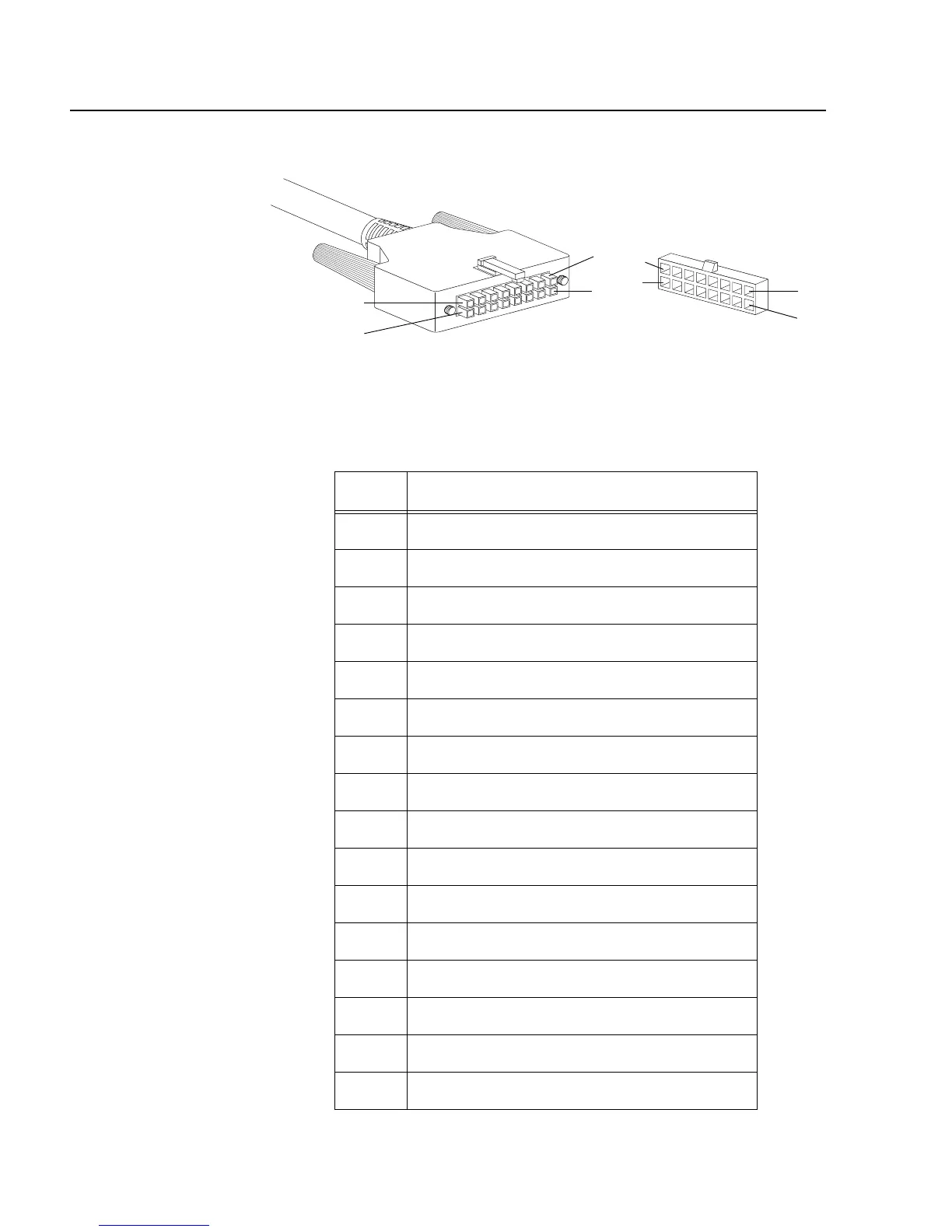
RPS 16-pin Molex Connector Port Pinouts
Figure 42 illustrates the pin layout to the 16-pin molex connector and
RPS port.
Figure 42. RPS 16-pin Molex Connector Pin Layout
Table 13 lists the 16-pin RPS connector pins and definitions.
Table 13. Pin Definitions of the 16-pin RPS Connector
Pin Definition
1+5V DC
2 Remote Sense (RS) +3.3 V DC
3 RS -3.3 V DC
4 RS +2.5V DC
5 Redundant Power Supply (RPS) present
6 +2.5V DC Return
7 +3.3V DC Return
8 +3.3V DC
9 +5V DC Return
10 +2.5V DC
11 +2.5 DC Return
12 +2.5V DC
13 +2.5V DC Return
14 +2.5V DC
15 +3.3V DC
16 +3.3V DC Return
16
8
9
1
9
1
16
8
 Loading...