AT-FS704 Installation Guide
3
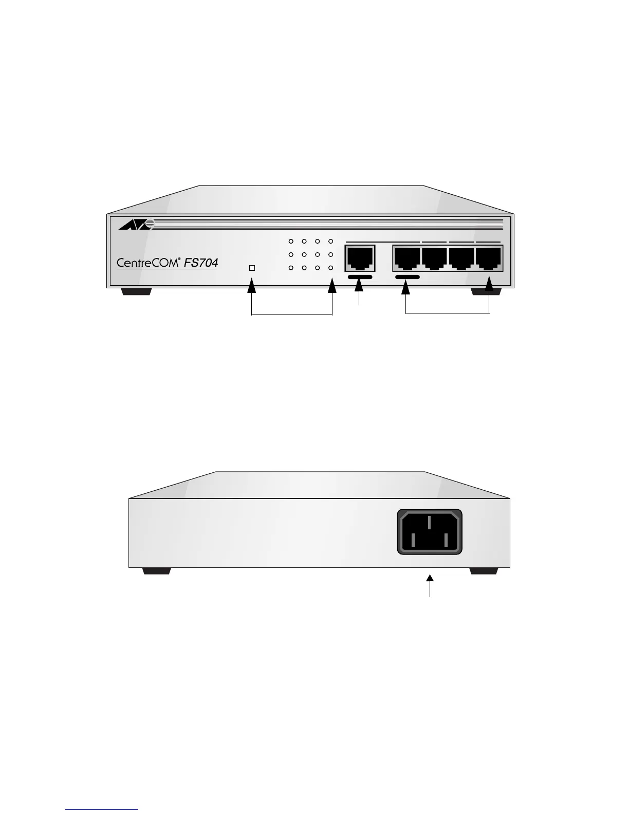
Physical Description
Front Panel
The AT-FS704 front panel consists of 4 (10/100 Mbps MDI-X) (Media
Dependent Interface with Crossover) ports, 1 Uplink (MDI) port and LED
indicators, as shown in Figure 2.
Figure 2
AT-FS704 Front Panel defined
Rear Panel
The rear panel of the AT-FS704 consists of an AC power connector, as shown
in Figure 3. Supported input voltages range from 100 ~ 240 V AC at 50 ~ 60 Hz.
Figure 3
Rear Panel View of the AT-FS704
1= X 2X 3X 4X
10BASE-T/100BASE-TX
4 PORT ETHERNET SWITCH
100M
LINK/ACT
FULL DUP
COLN
POWER
1234
To HUB To PC
LED Indicators
10/100M Ports (MDI-X)
Uplink Port (MDI)
POWER
AC Power Connector
 Loading...