Installation
12
As shown in Figure 8, when using straight cable, the connection is made from
the uplink (MDI) port of the switch to any port of the hub. Figure 8 also
demonstrates that the connection can be made from any (1X-4X) port of the
switch to any port of the hub when using crossover cable.
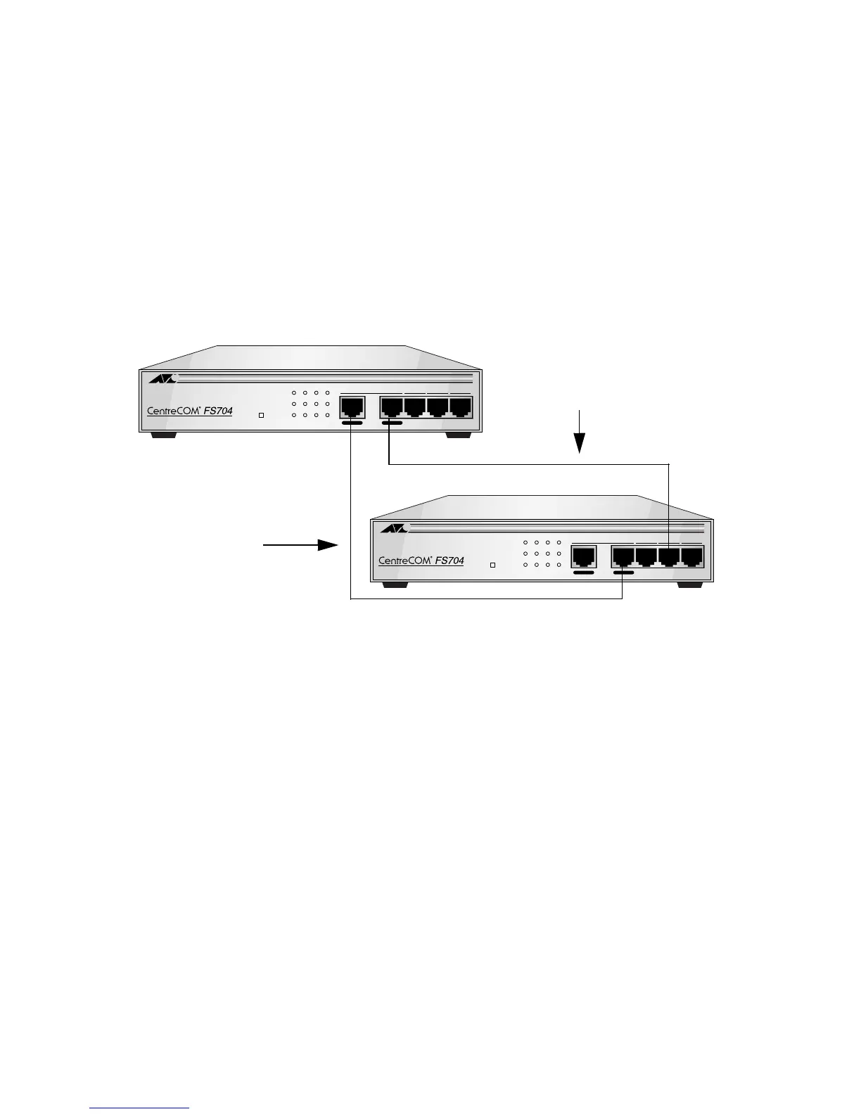
Switch-to-Switch Installation
The AT-FS704 switch can be connected to any switch or other device (routers
or bridges) using a two-pair Category 5 UTP/STP RJ45 straight or crossover
cable, as shown in Figure 9.
Figure 9
AT-FS704 Switch to Switch Connection Using the Straight or Crossover Cable Options
Figure 9 demonstrates using straight or crossover cable. When using straight
cable, connect the uplink (MDI) port of the switch (Switch A) to any 10 Mbps or
100 Mbps (MDI-X) port of the other switch (Switch B), or other device. When
using crossover cable, connect any (MDI-X) port of the switch (Switch A) to any
10 Mbps or 100 Mbps (MDI-X) port of the other switch (Switch B), or other
device.
1= X 2X 3X 4X
10BASE-T/100BASE-TX
4 PORT ETHERNET SWITCH
100M
LINK/ACT
FULL DUP
COLN
POWER
1234
To HUB To PC
1= X 2X 3X 4X
10BASE-T/100BASE-TX
4 PORT ETHERNET SWITCH
100M
LINK/ACT
FULL DUP
COLN
POWER
1234
To HUB To PC
Switch A
Straight Cable
Switch B
Crossover Cable
 Loading...