Installation
16
Standalone Configuration
In a standalone configuration, the switch supports up to 10 or 18 network
nodes, depending on the model. Figure 9 shows an 8-port switch connected to
end stations and a server. The basic physical connection for this configuration
requires connecting one of the switch’s ports to the adapter card of an end
station.
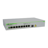
Figure 9: AT-RS710TX Connected to End Stations
Cascade Configuration
Cascading means that two switches can be connected together using any of the
switch ports provided you maintain the same medium type. Two switches can
be cascaded to support multiple network port connections. Cable length to the
nodes must follow the 100Base-TX cabling specifications.
To cascade installed switches (the 8-port models in this example), do the
following:
Note
When cascading switches, you must use the same medium type from
port to port. See also Table 5 for additional information.
1. If you intend to use a port with the MDI button, set MDI button to the
To HUB position (in).
2. Use a straight-through UTP RJ45 cable to connect the first switch to
the second switch. See Figure 10.
Cat 5, UTP wiring