10 x530 Series Quick Installation Guide
5. Repeat steps 2 to 4 to install the remaining bumper feet.
6. Turn the switch over.
7. Go to “Ports” on page 14.
Installing the Switch in an Equipment Rack
The following items are required to install the switch in an equipment
rack:
Two equipment rack brackets (included with the switch)
Eight M3x6mm bracket screws (included with the switch)
Cross-head screwdriver (not provided)
Four standard equipment rack screws (not provided)
To install the switch, perform the following procedure:
1. Place the switch on a table.
2. If the bumper feet are attached to the bottom of the switch,
remove them using a flat-head screwdriver.
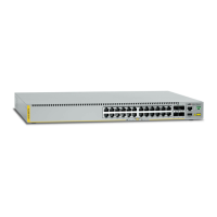
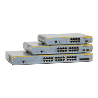
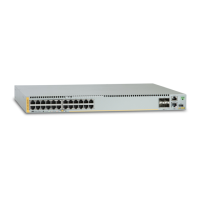
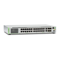
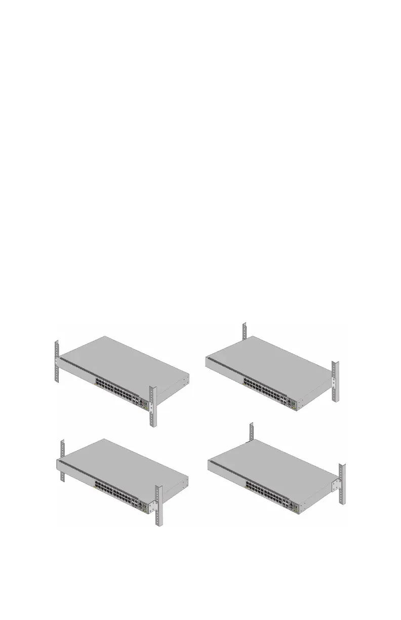
3. Attach two brackets to the sides of the switch with eight bracket
screws included with the unit. The following figures illustrate the
four possible positions of the brackets on the switch for a
standard 19-inch equipment rack.
 Loading...