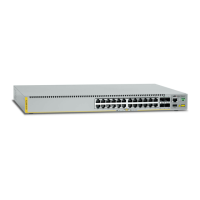
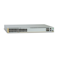
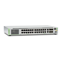
x530 Series Quick Installation Guide 11
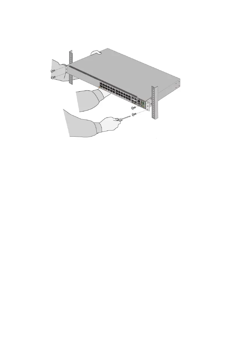
4. Have another person hold the switch in the equipment rack while
you secure it using four standard equipment rack screws (not
provided).
5. Go to “Ports” on page 14.
Installing the Switch on a Wall
You can install the switch on a wall with the front panel facing up, left,
or right. Do not install the switch with the front panel facing down.
Here are the required tools and material for installing the switch on a
wall:
x530-28GTXm and x530-28GPXm Switches: two wall/equipment
rack brackets and eight bracket screws (included with the
switches)
x530-28GPXm and x530-52GPXm Switches: four wall/equipment
rack brackets and sixteen bracket screws (included with the
switches)
Two or four wood or concrete wall screws (included with the
switch)
Two or four wall anchors (included with the switch)
Cross-head screwdriver (not provided)
Flat-head screwdriver (not provided)
Stud finder for a wooden wall, capable of identifying the middle of
wall studs and hot electrical wiring (not provided)
Drill and 1/4-inch carbide drill bit for a concrete wall (not provided)
 Loading...