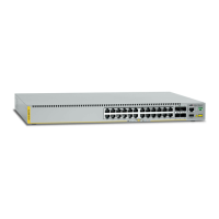
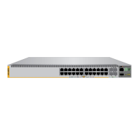
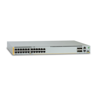
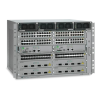
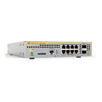
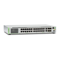
14 x530 Series Quick Installation Guide
6. Place the switch on a table.
7. Use the stud finder to check for hot electrical wires at the
locations of the screw holes.
8. If the wall material requires pre-drilling the screw holes, use an
appropriate drill to drill the holes. The dimensions of the supplied
screws and anchors are in “Unpacking the Switch” on page 7.
9. If the wall material requires anchors, insert the anchors into the
screw holes.
10. Have another person hold the switch at the selected wall location
while you secure it to the wall with appropriate screws.
11. Go to “Ports” next.
Ports
Ethernet Copper Cable Specifications
The minimum cable requirements for the Ethernet copper ports are.
10/100Mbps ports: Standard TIA/EIA 568-B-compliant Category
3 unshielded cabling.
1000Mbps ports: Standard TIA/EIA 568-A-compliant Category 5
or TIA/EIA 568-B-compliant Enhanced Category 5 (Cat 5e)
unshielded cabling.
1/2.5/5Gbps ports: Standard TIA/EIA 568-A-compliant Category
5 or TIA/EIA 568-B-compliant Enhanced Category 5 (Cat 5e)
unshielded cabling.
Cabling Ethernet Copper Ports
Observe the following guidelines when connecting Ethernet copper
cables to the ports on the switch:
The connectors on the cables should fit snugly into the ports, and
the tabs should lock the connectors into place.
The default speed setting for the ports is Auto-Negotiation. This
setting is appropriate for ports connected to network devices that
also support Auto-Negotiation.
Warning: Do not install the switch on a wall near hot
electrical wires.
 Loading...
