EasyManuals Logo

Allied Telesis x530 Series Quick Installation Guide

Allied Telesis x530 Series
24 pages
To Next Page IconTo Next Page
To Previous Page IconTo Previous Page
Page #7 background imageLoading...
Page #7 background image
x530 Series Quick Installation Guide 7
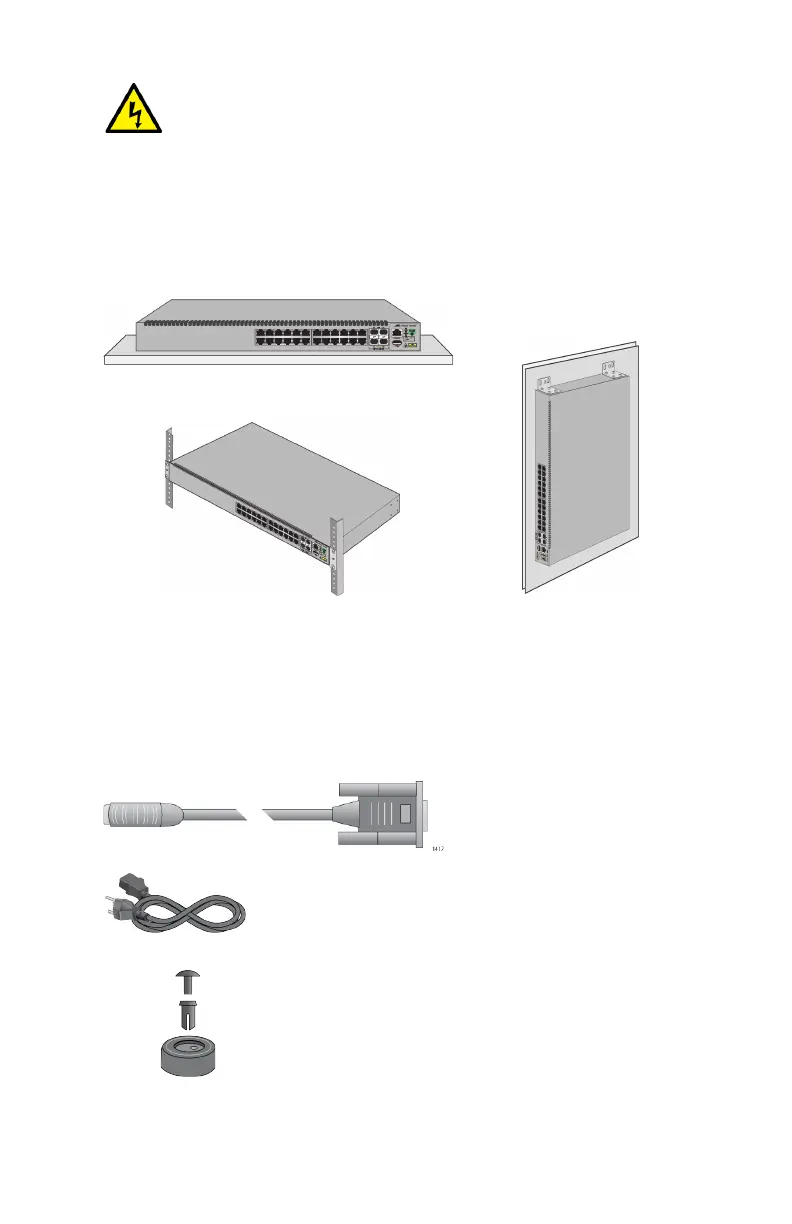
Installation Options
This figure illustrates the installation options.
Unpacking the Switch
Here are the accessory items that come with the switches.
Warning: To reduce the risk of electric shock, the PoE
ports on this product must not connect to cabling that is
routed outside the building where this device is located.
E40
Table
Standard 19-inch
equipment rack
Wood or concrete
wall
One 2m (6.6 ft) local
management cable with
RJ-45 (8P8C) and DB-9
(D-sub 9-pin) connectors.
Two AC power cords
Four bumper feet with rivets

Other manuals for Allied Telesis x530 Series

Questions and Answers:

Question and Answer IconNeed help?

Do you have a question about the Allied Telesis x530 Series and is the answer not in the manual?

Allied Telesis x530 Series Specifications

General IconGeneral
BrandAllied Telesis
Modelx530 Series
CategorySwitch
LanguageEnglish

Related product manuals