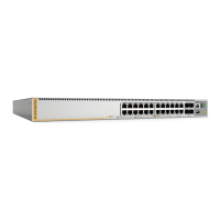
8 x530 Series Quick Installation Guide
Choosing a Site for the Switch
Review these site recommendations and requirements.
Before installing the switch in an equipment rack, check that the
rack is safely secured so that it will not tip over. Devices in a rack
should be installed starting at the bottom of the rack, with the
heavier devices near the bottom.
Before installing the switch on a table, verify that the table is level
and stable.
Before installing the switch on a wall, verify that the wall’s material
is strong enough to hold the switch’s weight. You should position
the device so that it can be screwed into the wall’s framing timber
or equivalent structural element.
The power outlet should be located near the switch and be easily
accessible.
The site should allow for easy access to the ports on the front of
the switch so that you can easily connect and disconnect cables,
and view the port LEDs.
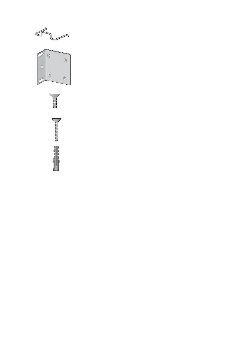
Two power cord retaining clips
Wall/equipment rack brackets:
2 brackets - x530-28GTXm and x530-28GPXm
4 brackets - x530-52GTXm and x530-52GPXm
Bracket screws: 3x6mm
8 screws - x530-28GTXm and x530-28GPXm
16 screws - x530-52GTXm and x530-52GPXm
Wood and concrete wall screws: 4x32.3mm
2 screws - x530-28GTXm and x530-28GPXm
4 screws - x530-52GTXm and x530-52GPXm
Wall anchors - 6x4x29.6mm:
2 anchors - x530-28GTXm and x530-28GPXm
4 anchors - x530-52GTXm and x530-52GPXm
 Loading...