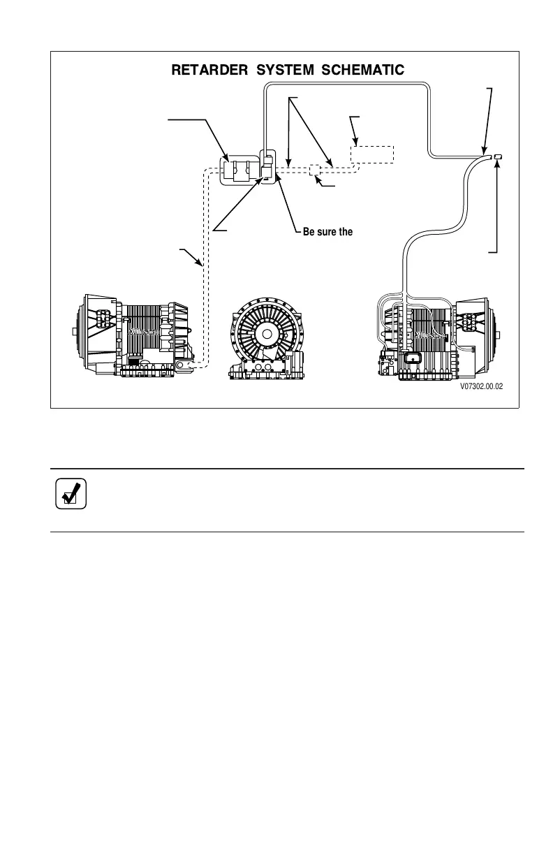
NOTE: Be sure a pressure protection valve is correctly installed
between the vehicle brake air system and the accumulator control
solenoid.
1. Connect the air supply hose fitting to the retarder air control solenoid.
Tighten the fitting to 16–22 N•m (12–16 lb ft).
2. Connect the hydraulic hose between the retarder and the accumulator.
Tighten hose fittings to 68–81 N•m (50–60 lb ft).
6–6. CONNECTING POWER TAKEOFF CONTROLS
If not already mounted, mount the PTO(s) onto the transmission (refer to Section
4–3, Installing PTO).
1. Inspect the PTO harness routing for kinks and sharp bends. Avoid routing
the cable close to exhaust pipes or manifold. The PTO harness must not
rub or interfere with adjacent parts.
2. Connect controls to the PTO.
3. Determine if PTO control operation is correct.
RETARDER
ACCUMULATOR
AND MOUNTING
BRACKETS
AIR SUPPLY HOSE
VEHICLE
ACCESSORY
AIR TANK
VEHICLE
WIRING
HARNESS
IN-CAB
TRANSMISSION
CONTROLS
RETARDER
SOLENOID
NORMALLY
CLOSED
PRESSURE PROTECTION
VALVE (85 PSIG
MAXIMUM CLOSING
PRESSURE)
Tie down center
of hose if longer
than 0.9 m (3 ft).
RETARDER SYSTEM SCHEMATIC
V07302.00.02
Be sure there is an
orifice fitting on
T400 installations
(and is not present
on T200/T300
installations).
Figure 6–1. 3000 And 4000 Product Families Output Retarder
Accumulator Installation
71

 Loading...