Copyright © 1998 General Motors Corp. G–1
WTEC II ELECTRONIC CONTROLS TROUBLESHOOTING MANUAL
APPENDIX G — MISCELLANEOUS ITEMS
1–1. WELDING ON VEHICLE
When frame or other welding is required on the vehicle, take the following precautions to protect the electronic
control components:
1. Disconnect the wiring harness connectors at the transmission electronic control unit.
2. Disconnect the positive and negative battery connections, and any electronic control ground wires
connected to the frame or chassis.
3. Cover electronic control components and wiring to protect them from hot sparks, etc.
4. Do not connect welding cables to electronic control components.
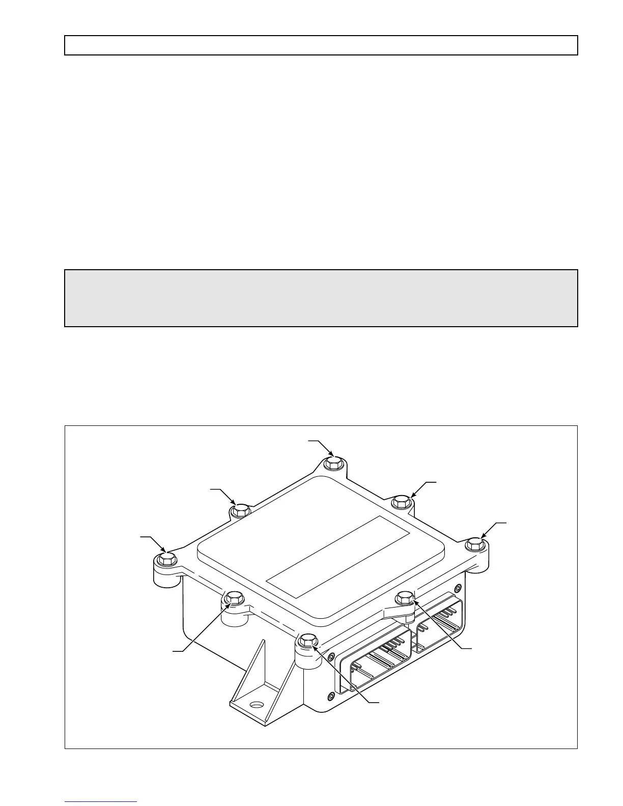
1–2. VEHICLE INTERFACE MODULE
The Allison Vehicle Interface Module (VIM) containing all Allison system relays and fuses must be used as the
interface to all vehicle wiring. Refer to Figure G–2 for VIM component location and pin-out. To close an open
VIM, tighten the bolts in the numerical order shown in Figure G–1 to provide a sealed, water-tight box. Torque to
the bolts to 5–8 N·m (4–6 lb ft).
Figure G–1. Vehicle Interface Module (VIM)
WARNING!
Do not jump start a vehicle with arc welding equipment. Arc welding
equipment’s dangerously high currents and voltages cannot be reduced to safe
levels.
4
6
8
1
3
7
2
5
V00657