Copyright © 1998 General Motors Corp. 6–43
DIAGNOSTIC CODES
WTEC II ELECTRONIC CONTROLS TROUBLESHOOTING MANUAL
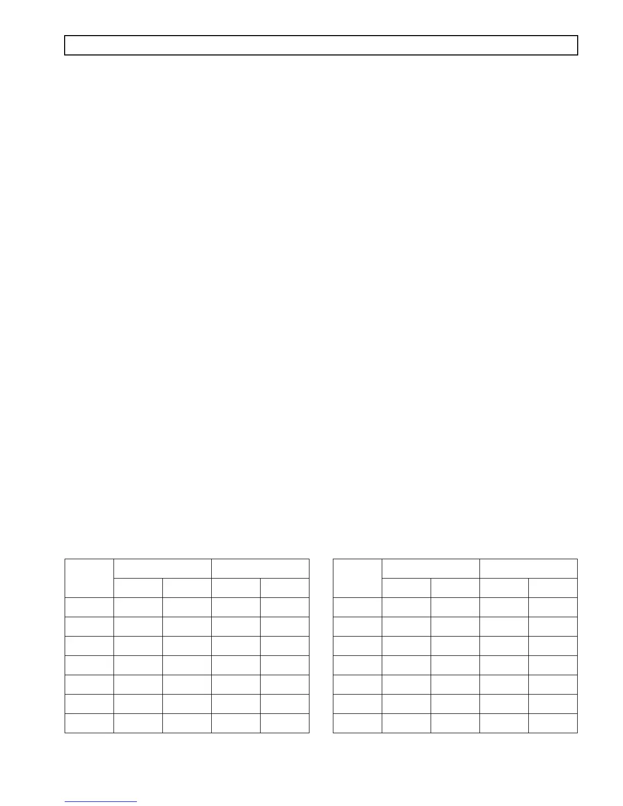
Table 6–5. External Hydraulic Circuit Characteristics
Non-Retarder, PTO, 93°C (200°F) Sump Temperature
HD/B 500
B. Code 24 23:
1. Install temperature gauges for transmission temperature and engine water temperature. Drive the
vehicle. Verify the code can be reproduced and verify the reading shown on the diagnostic tool.
Observe the gauges and check for hot fluid when the code is produced.
2. If the fluid is not hot when the code is produced, remove the connectors at the ECU and the
transmission. Check the fluid temperature sensor wiring for opens, shorts, and shorts-to-ground.
Compare the resistance readings of the sensor and the actual temperature as shown on the gauge
with Figure 6–12 on previous page. If wiring problems or a great difference between temperature
and resistance compared with the chart are found, drain the fluid, remove the control module, and
replace the temperature sensor (refer to the Service Manual for the transmission being checked). If
wiring problems are found, repair or replace as necessary.
3. If the fluid is hot when the code is produced, observe the gauges to see if the engine became hot
before the transmission. If the engine cooling system is overheating and heating the transmission,
the problem is with the engine or its cooling system.
4. If the transmission became hot before the engine, allow the vehicle to idle for 3–5 minutes and
check the transmission fluid level. Correct the fluid level if necessary.
5. Attach pressure gauges to the cooling system (from a “to cooler” connection to a point after the
cooling circuit filter) and check for pressure drop problems. If pressure drop is excessive (refer to
Table 6–5), check for a plugged cooler filter, collapsed lines, obstructions, etc.
6. If the fluid level is correct and the cooling circuits satisfactory, drain the fluid, remove the control
module, and inspect for damaged valve body gaskets. Replace any damaged gaskets (refer to the
appropriate transmission Service Manual).
7. If no problems are found in the control module area, remove the transmission and
disassemble, inspecting for causes of overheating (stuck stator, plugged orifices, dragging
clutches, etc.). (See the Service Manual for the transmission being checked.)
CODE 24 XX — SUMP FLUID TEMPERATURE (Figures 6–10, 6–11)
CONVERTER OPERATION
MAXIMUM
COOLER FLOW
Input
rpm
Flow Pressure Drop
L/s gpm kPa psi
600 0.22 3.4 0 0
900 0.38 6.1 0 0
1200 0.55 8.7 0 0
1500 0.80 12.7 0 0
1800 1.03 16.4 0 0
2100 1.13 18.0 0 0
2300 1.20 19.0 0 0
CONVERTER OPERATION
MAXIMUM ALLOWABLE
PRESSURE DROP
Input
rpm
Flow Pressure Drop
L/s gpm kPa psi
600 0.20 3.2 31 4.5
900 0.37 5.8 63 9.1
1200 0.55 8.7 108 15.7
1500 0.77 12.2 167 24.2
1800 0.92 14.5 213 30.9
2100 0.97 15.3 238 34.5
2300 1.00 15.9 250 36.3