WTEC II ELECTRONIC CONTROLS TROUBLESHOOTING MANUAL
P–22 Copyright © 1998 General Motors Corp.
APPENDIX P — INPUT/OUTPUT FUNCTIONS
WARNING!
These schematics show the intended use of the specified controls features which
have been validated in the configuration shown. Any miswiring or use of these
features which differs from that shown could result in damage to equipment or
property, personal injury, or loss of life. ALLISON TRANSMISSION IS NOT
LIABLE FOR THE CONSEQUENCES ASSOCIATED WITH MISWIRING
OR UNINTENDED USE OF THESE FEATURES.
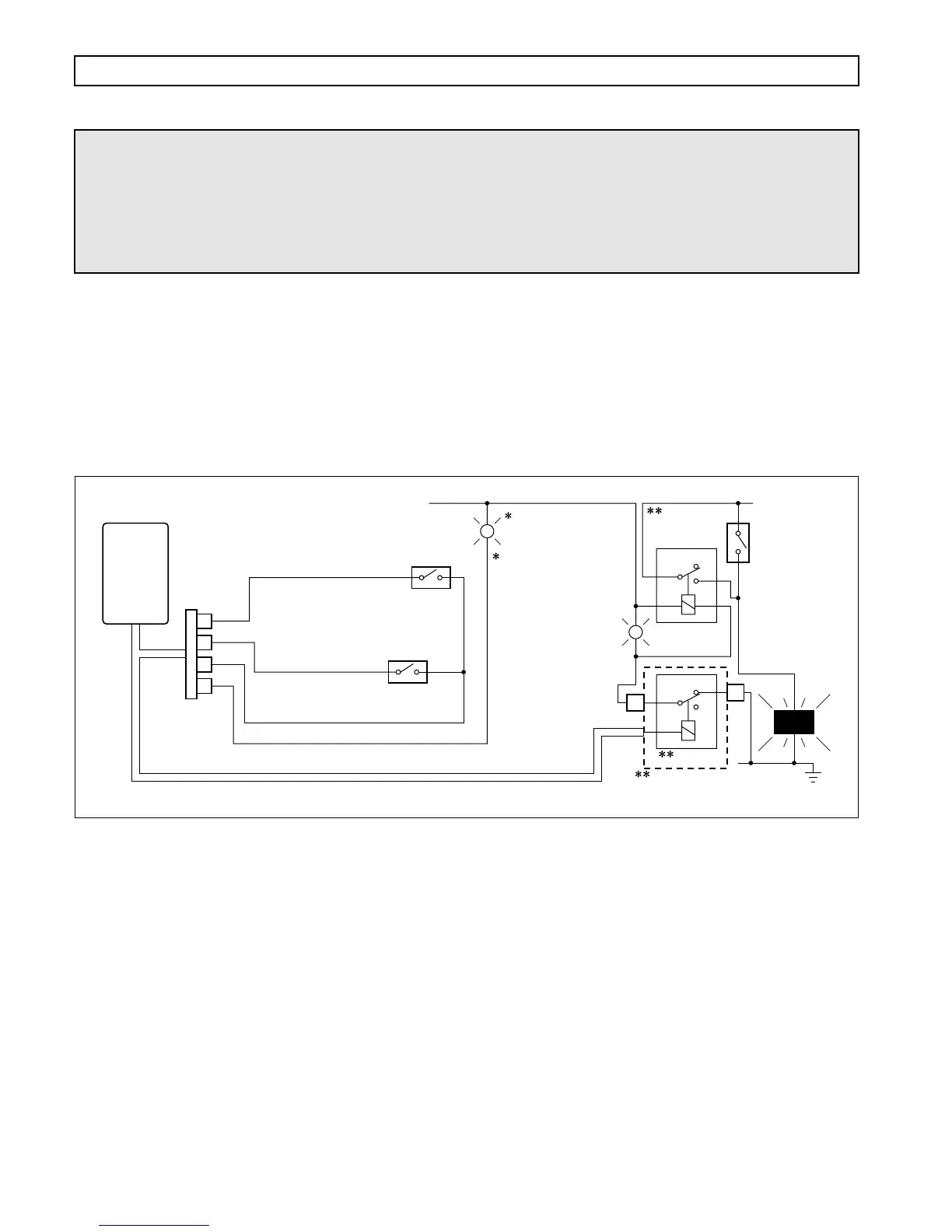
RETARDER ENABLE
USES: Provides for operator ON/OFF control of the retarder, transmission temperature indication, and brake
lights during retarder operation.
USES: None
VOCATIONS: Various. This function is required for retarder-equipped transmissions.
Figure P–22. Retarder Enable
V05027
WIRE 163
RETARDER ENABLE
WIRE 125
RETARDER INDICATOR
WIRE 137
SERVICE BRAKE STATUS
RETARDER
ON
TRANS
TEMP
(YELLOW)
WIRE 161B SIGNAL GROUND
WIRE 105
RETARDER OR SUMP TEMP
RETARDER
DASH SWITCH
Closed = On
Closed =
Brakes On
BRAKE
PEDAL SWITCH
Relays shown
de-energized
CUSTOMER-
FURNISHED
RELAY
BRAKE
LIGHTS
SWITCH
BRAKE
LIGHTS
SWITCHED
POWER
UNSWITCHED
POWER
E1
NC
COM
VIM
NO
NC
COM
NO
D1
NOTE: If vehicle is equipped
with air brakes, this switch
should close at 2 – 5 psi.
NOTE: Use of this light
is optional with a transit
bus or when using a
transmission temp gauge.
If current in lamp circuit
exceeds 0.5 amp, ground
lamp through a relay
1
13
14
5
VIW
CONNECTOR
ECU