8. Operation with Multiple SG1s CONTINUED
Shaw Almex Industries | 1.800.461.4351 | www.almex.com
Revised - April 2014 49900-038
FUNCTIONALITY SLAVE MASTER
SET SPLICE PARAMETERS
•
START SPLICE
•
E-STOP SPLICE
• •
MODIFY ALARMS
• •
USB COMMUNICATION
•
WIFI COMMUNICATION
•
ITEM QUANTITY
FEMALE TERMINATOR 1
MALE TERMINATOR 1
TEE FITTING 1 PER CONNECTED SG1
NETWORK CABLE 1 PER CONNECTED SG1
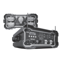
FIGURE 31: CONNECTIONS FOR AN SG1 NETWORK WITH 2 UNITS
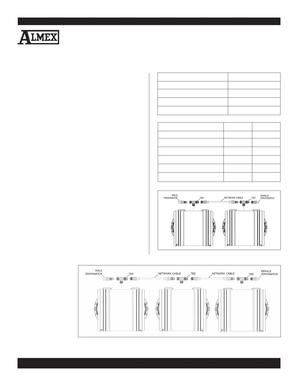
FIGURE 32: CONNECTIONS FOR A NETWORK WITH 3 SG1 UNITS
12
In an SG1 network, one unit is designated as a network master.
It is responsible for synchronizing communication between all
SG1s in the network. The Master has full control of the other
units and is the single point of contact for communication with
ALMEXPADs. The master SG1 can be identified because its
Network Master LED is emitting a solid, non-flashing light.
All other units are referred to as Slave units. These units have
less functionality and are for the most part controlled by the
master unit. They are identified by flashing LEDs.
8.2. PREPARATION
The SG1s are connected via DeviceNet network cables. These
cables are industrial rated for use in electrically noisy environ
-
ments and are designed to be immune to inductive interfer-
ence. The steps you will need to perform in order to form an
SG1 network are as follows:
1. Connect each tee fitting to the networking receptacle on the
rear panel of each SG1.
2. Connect the network cables in between adjacent SG1s.
3. Add the male and female terminators to the 2 unterminated
tees of the end SG1s. (See FIGURES 31 & 32)
4. Power up all SG1s.
5. Select a single SG1 to be the master. For best performance
select the central SG1 (one without a terminator in a network
with 3 or 4 SG1s). On that unit navigate to the “Settings”menu
and select the network type option to initialize the unit as the
“master”. Connected SG1s (unless they are active in a splice
operation) will automatically be configured as slaves. After
network configuration, the master can be operated in the
same way as a single basic unit. A splice can be configured
and started from the “Splice Info” menu. The master SG1
can communicate with
and be controlled by an
ALMEXPAD via USB or
WiFi.
6. The Platen Switches on
each unit must be set to
AUTO in order to oper
-
ate under a networked
splice.