Shaw Almex Industries | 1.800.461.4351 | www.almex.com
6
Revised - April 2014 49900-038
SG1 FRONT PANEL
3.1. WIFI ANTENNA
Allows the SG1 Switchgear Box to connect wirelessly to
ALMEXPAD Senior and exchange data.
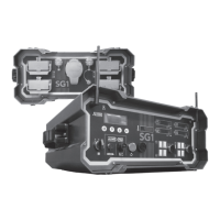
3.2. PLATEN SET 1 AND PLATEN SET 2 SWITCHES
The main heating controls are
located on the left side of the SG1
front panel.
Each control, can be
set in the AUTO, OFF, or
MANUAL position. In AUTO mode,
the SG1 controls the splice
according to the splice parameters
set using the ALMEXPAD or SG1
menus. Holding a platen switch
in the MANUAL position forces
the platens on without the
use of
the temperature controller.
(SEE FIGURE 5)
3.3. AUXILIARY SWITCH
Controls power to the auxiliary receptacles for an Almex Pres-
sure Pump. Power is ON when set in the MANUAL position.
Note: The AUTO mode is non-operational at this time and
should not be used.
(SEE FIGURE 5)
3.4. USB CABLE RECEPTACLE
Allows the user to connect to the ALMEXPAD tablet. The connection
has a threaded cap to create a water-tight seal
.
(SEE FIGURE 6)
3.5. RESET BUTTON
Restarts the SG1. (SEE FIGURE 6)
NOTE: The reset button does not need to be pressed to
prepare for the next heat cycle. This is handled automati
-
cally once a splice is completed.
3.6. WARNING ALARM
Indicates that the SG1 or attached press is operating outside of
recommended and/or desired operating conditions. The SG1
gives an audible signal if the splice is outside of a user specified
temperature range, current range, pressure range or if a platen
cable is disconnected. (SEE FIGURE 6) (For more information
SEE ALARMS, SECTION 4.3)
3.7. TABLET POWER RECEPTACLE
Provides DC power to charge and run ALMEXPAD Senior or
Junior Tablets.
(SEE FIGURE 6)
3.8. THERMOCOUPLE RECEPTACLES
Located on the right side of the SG1 front panel. These
receptacles serve as further inputs for tracking and recording
platen temperature. NOTE: Use K-Type thermocouples only.
(SEE FIGURE 7)
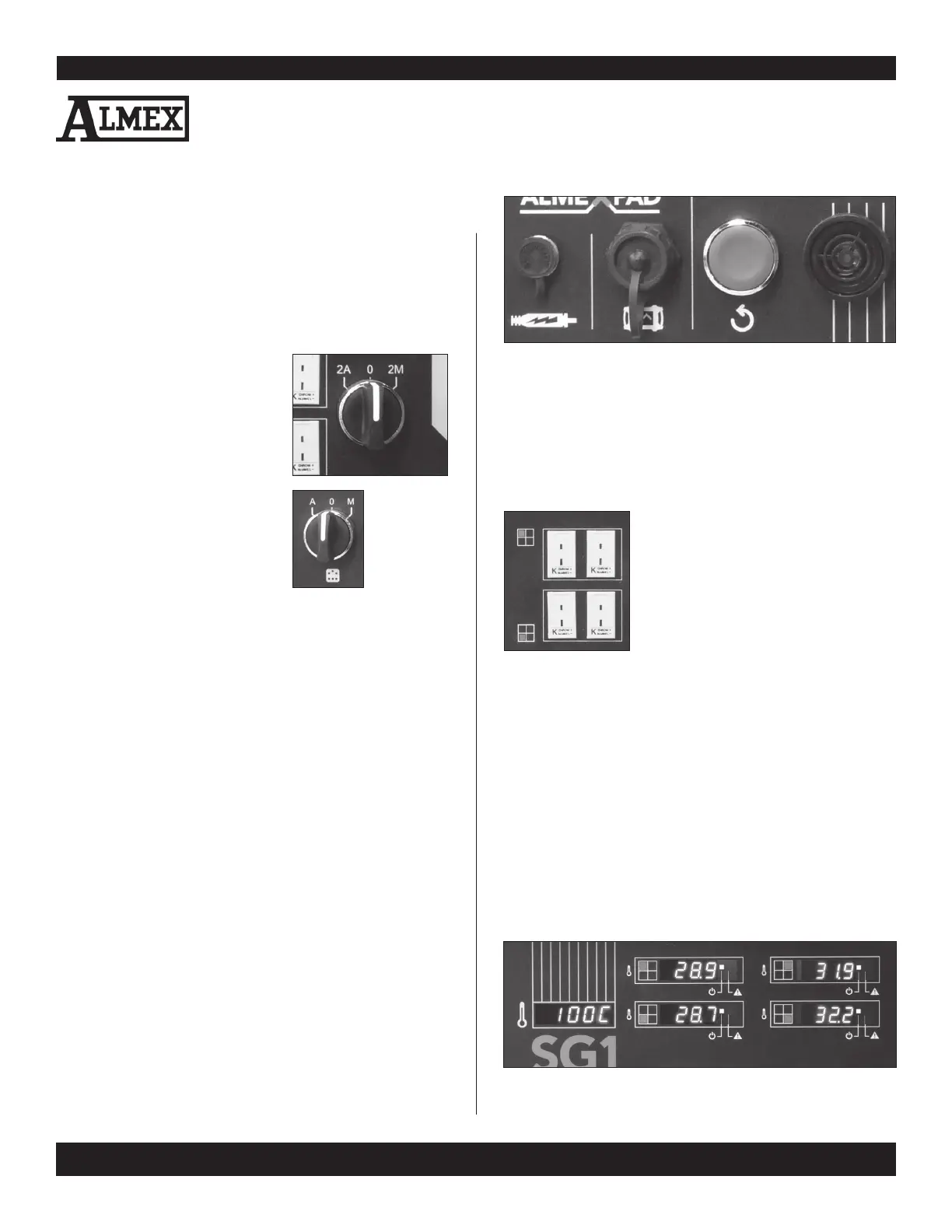
FIGURE 8 - BOTTOM LEFT - TEMPERATURE SET POINT INDICATOR
CENTRE TOP & BOTTOM - PLATEN SET 1 TEMPERATURE INDICATORS
RIGHT TOP & BOTTOM - PLATEN SET 2 TEMPERATURE INDICATORS
FIGURE 7 - THERMOCOUPLE RECEPTACLES
3. Hardware Overview
FIGURE 6 - FROM LEFT TO RIGHT - USB CABLE RECEPTACLE, TABLET POWER
RECEPTACLE, RESET BUTTON, WARNING ALARM
3.9. TEMPERATURE SET POINT INDICATOR
Displays the goal termperature of the splice recipe’s current
phase. (SEE FIGURE 8)
3.10. PLATEN SET 1 AND 2 TEMPERATURE INDICATORS
Displays the current temperature of the connected platens.
(SEE FIGURE 8)
3.11. PLATEN ON LED
Illuminates if the platen is on. (SEE FIGURE 8)
3.12. SET POINT REACHED LED
Illuminates if the platen has reached the set point for the
current phase. (SEE FIGURE 8)
FIGURE 5 -
PLATEN SET
2 (TOP) AND
AUXILIARY
SWITCHES
(LEFT)