20
We reserve the right to modify technical specifications without prior notice.
UK830532/200610 © Alpha-InnoTec GmbH
CAUTION.
Make sure to equip the power supply of
the heat pump with a 3-pole automatic
cut-out with at least 3mm contact gap.
Note the level of the release current.
Overview “Technical data/scope of delivery”,
“Electric” section.
CAUTION.
If using the unit in 3~230V systems, please
note that the residual-current circuit
breaker (RCCB) used must be AC-DC sen-
sitive.
heatpumpsideConneCtionoftheControland
sensorWires
The heat pump is connected to the heating and heat
pump regulator by means of the control and sensor
wires. They are connected at the electric switch cabi-
net on the switch cabinet side (= operator side) of the
heat pump.
DANGER!
Danger of fatal injury due to electric cur-
rent!
Unit must be disconnected from the pow-
er supply.
lW71…/lW81…:
Proceed as follows:
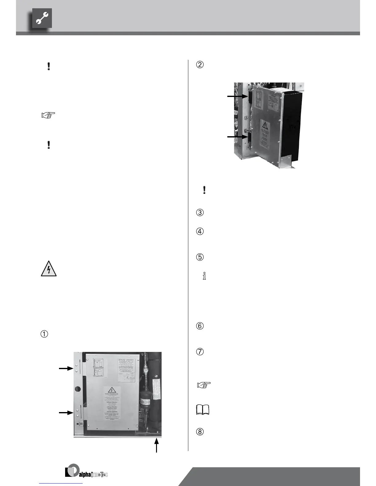
Loosen mounting screws of the electric switch
cabinet inside the unit…
Suspend electric switch cabinet outside in the pro-
vided recesses of the frame…
CAUTION.
Do not tip electric switch cabinet.
Screw control and sensor wires to the two connec-
tors on the back of the electric switch cabinet…
After connecting the control and sensor wires, fas-
ten the electric switch cabinet in its original posi-
tion…
Guide control and sensor wires out of the unit…
NOTICE.:
In order to enable unhinging of the elec-
tric switch cabinet in the event that cus-
tomer service is necessary, the control
and sensor wires in the heat pump must
have an excess length of about 15 cm.
Install control and sensor wires in a conduit as far
as where they enter the building and from there on
to the heating and heat pump regulator…
Connect control and sensor wires to the heating
and heat pump regulator according to the terminal
diagram and the circuit diagrams for the respective
model…
“Terminal diagrams” and “Circuit diagrams” for
the respective model.
Operating manual of the heating and heat pump
regulator.
Seal empty pipes on unit side…