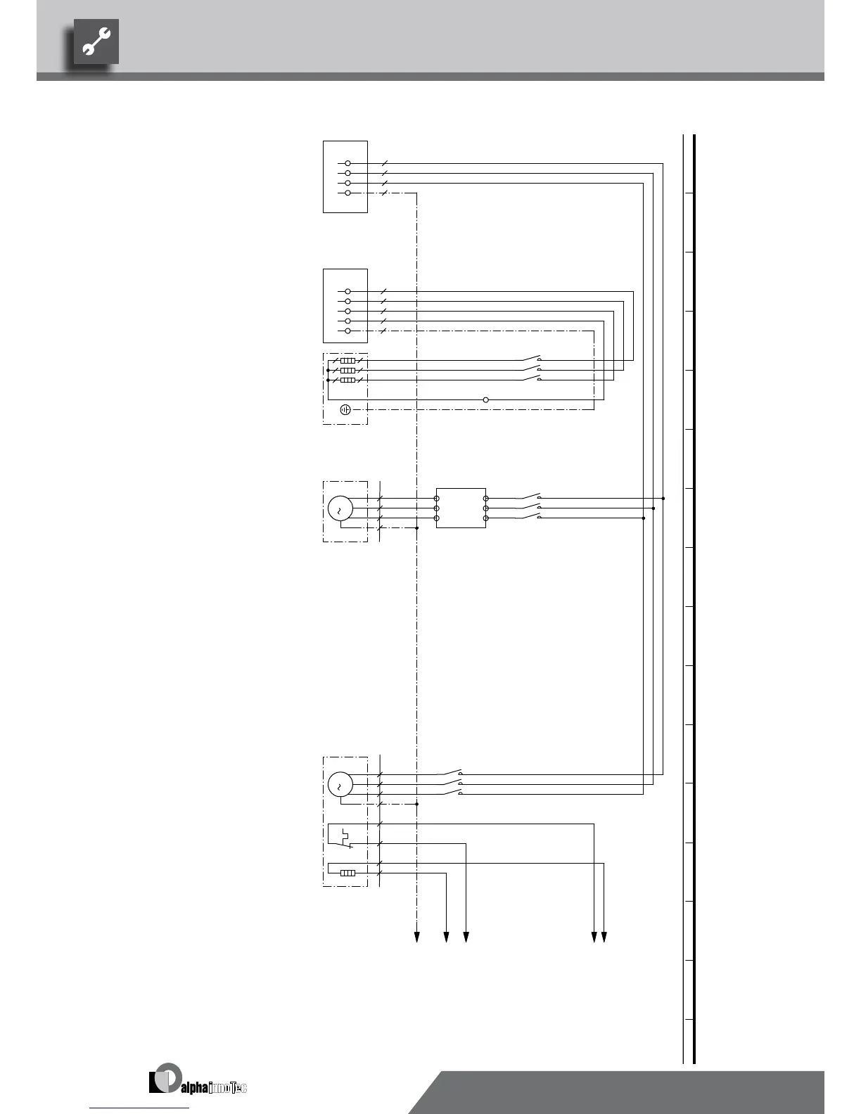
52
L1
-X8
L2 L3 PE
1L1
-X9
1L2
1L3
1N-
1PE
1
2
-Q5
/2.7
-E22
ZW1
3
4
5
6
1N
-X10
1
2
-Q1
/2.5
3
4
R S T
U V W
-Q11
M
3
T1
T2
T3
PE
-M1
VD1
5
6
1
2
-Q3
/2.6
3
4
M
3
U1
V1
W1
PE
-G3
VENT1
5
6
TK
TK
-E23
N Reg
/2.2
L Reg
/2.2
MOT
/2.2
E23
/2.2
PE
/2.2
6
Nozzle heating fan
2
E23
gn/ge
PE
VENT1
Distribution box power supply additional heating
Legend:
Fan
3~N/PE/400V/50Hz
Q11
1
X8
1 3
5
Contactor for compressor 1
Terminal in switch box heat pump
X10
gn/ge
G3
Starting current limit
1
-G3
Function
X9
4
VD1
5
VD1
3~PE/400V/50Hz
Q1
1
Power supply compressor; right-hand rot. field is mandatory!
UK817332
F3
Distribution box power supply output compressor
Q3
6
-F3
ZW1
2
E22
2
2
3~PE/400V/50Hz
7
1
Contactor fan
43
Motor protection fan
-M1
3
Contactor for auxiliary heating
3
Power supply aux. heating
3 4
M1
Auxiliary heating
Q5
Compressor 1
ZW1
VBO
Operating materials
PE2
3~N/PE/400V/50Hz
We reserve the right to modify technical specifications without prior notice.
UK830532/200610 © Alpha-InnoTec GmbH
LW 71A • LW 81A Circuit diagram 1/2