LR
A
≥...
Aufstellungsplan ist gültig für:
PL 2009 und älter: LW 100A-120A, LW 150HA
PL 2010, LW 101A, LW 150HA
8
7
6
5
4
3
2
1
Schutzvermerk nach DIN 34 beachten
1
1
Ers. d.
Ers. f.
A
B
C
D
E
F
F
E
D
C
B
A
4
3
2
1
Benennung
Aufstellungs- Sockelplan
LW 100A, 101A/120A, LW 150HA
819375
-
Zust.
Änderungstext
PEP 026/2009
Datum
18.3.2010
RA
Von
Blatt
von
Werkstoff
Gewicht
Maßstab
1:50
1:30
Det. Maßstab
Datum
Name
Erstellt
Gepr.
Norm.
18.3.2010
Aepfelbach
18.3.2010
Aepfelbach
toleranz
Allgemein-
Oberflächen
ArtikelNr.
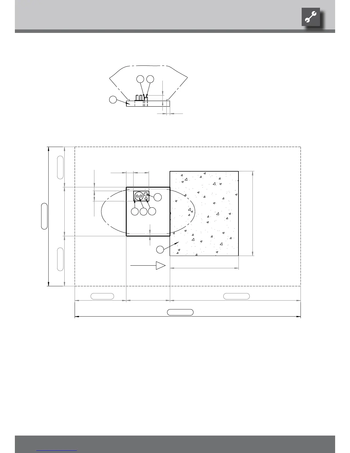
Legend: UK819375
All dimensions in mm.
A Front view
C Top view
≥ … Minimum clearances
1 Recess in base
2 Local heat pipe for heating water forward/return ow
3 Empty pipe for electric cables, minimum diameter 70mm
4 Condensate discharge, minimum diameter 50mm
5 water-permeable surface (gravel, …) in the air outlet area
6 Base
LR Air direction
We reserve the right to modify technical specifications without prior notice.
UK830532/200610 © Alpha-InnoTec GmbH
Installation plan LW 101… • LW 150H…