53
N Reg
/1.14
E23
/1.14
L Reg
/1.14
MOT
/1.14
PE
/1.14
12
-X12
L
-X10
6
27
11
N
P
+-
b2 c4
a1
-F1
HDP
5
1 2
/1.7
3 4
/1.7
5 6
/1.7
21 22
1
A1
A2
-Q1
VD1
1 2
/1.11
3 4
/1.12
5 6
/1.12
21 22
10
A1
A2
-Q3
VBO
7
28
-X10
-K10
1 2
/1.4
3 4
/1.5
5 6
/1.5
21 22
8
ϑ
-STB
A1
A2
-Q5
ZW1
3
P
+-
c4
a1
-F2
NDP
P
- +
c4
a1
-B10
AEP
9
-X12
ϑ
1
-X52
-R4
TRL
2
ϑ
3
-R5
TVL
4
ϑ
5
-R6
THG
6
ϑ
7
-R3
TWA
8 9
29
-X7
-R10
CW
10
30
ϑ
11
-R2
TWE
12
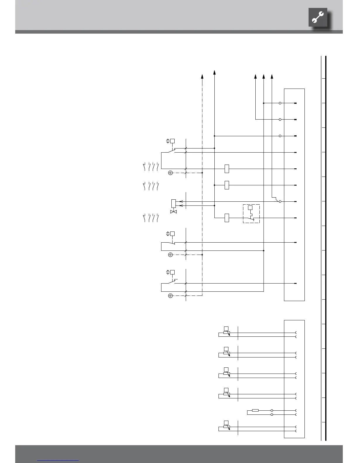
NDP
F1
STB
Low-pressure switch
K10
VBO Contactor fan
Q5
Legend:
AEP
-X12
TRL
-X52
R3 If installed: heat source outlet gauge
TVL
Hot gas sensor
UK817332
TWA
ZW1
Defrosting valve
B10
Plug on switch box heat pump (control line)
High-pressure switch
Q1
Defrosting pressostat
X12
Safety temperature limiter heating element
Contactor for compressor 1
Contactor for auxiliary heating
Q3
Function
F2
Terminal in switch box heat pumpX10
HDP
PE
-K10 -F2
VD1
Operating materials
R2
N ND
bl
THGTRL
L1
PE
-F1
VD1 AV
TWA
HD
bl
ZW1MOT VBO
X52
2
R6
-B10
ASD
bl
THG
R4
R5
TVL
TWE
Flow sensor
Encoding resistor, 442 Ohm
bl
R10
rt 1 PE
Return sensor
If installed: heat source input gauge
Plug on switch box heat pump (gauge line)
CW
TWE
We reserve the right to modify technical specifications without prior notice.
UK830532/200610 © Alpha-InnoTec GmbH
Circuit diagram 2/2 LW 71A • LW 81A