66
L Reg
/1.12
MOT
/1.12
R23
/1.12
N Reg
/1.12
PE
/1.12
12
-X12
L
-X7
6 11
N
P
+-
b2 c4
a1
-F1
HDP
5
1 2
/1.7
3 4
/1.7
5 6
/1.8
1
A1
A2
-K1
VD1
2
-X7
ϑ
-E2
3
-Y2
N PE
7
-X12
1
-Y1
N
1 2
/1.9
3 4
/1.9
5 6
/1.10
10
A1
A2
-K3
3
P
+-
c4
a1
-F2
NDP
1 2
/1.5
3 4
/1.5
5 6
/1.5
8
-X12
ϑ
-STB
A1
A2
-K5
ZW1
P
- +
c4
a1
-E1
AEP
9
ϑ
1
-X52
-R4
TRL
2
ϑ
3
-R5
TVL
4
ϑ
5
-R6
THG
6
ϑ
7
-R3
TWA
8 9
29
-X7
-R10
CW
10
30
ϑ
11
-R2
TWE
12
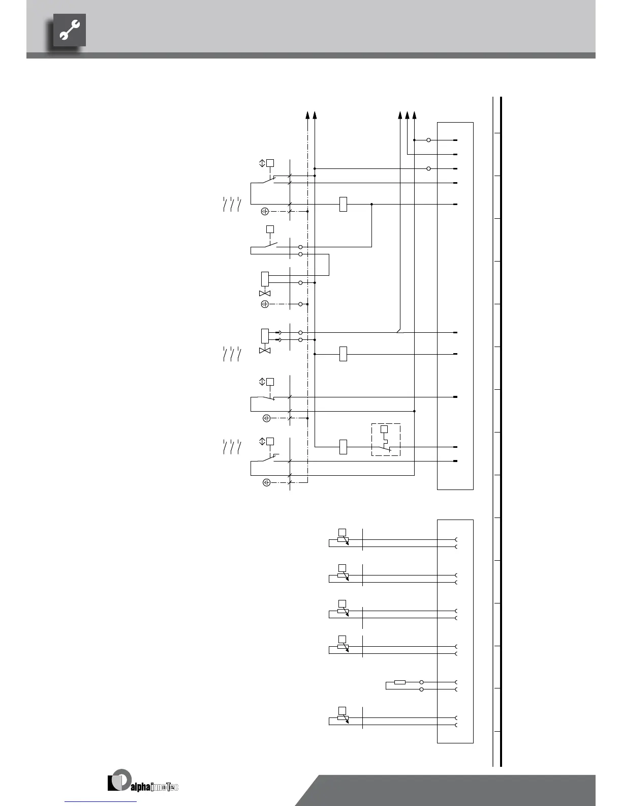
TWA
Hot gas thermostat gas injection compressor
If installed: heat source input gauge
-E2
TWE
E2
If installed: heat source outlet gauge
R2
R3
TWA
Solenoid valve gas injection compressor
TRL
STB
Plug on switch box heat pump (control line)
TVL
K5 Contactor for auxiliary heating
L1
NDP
Y2
ZW1
PE
ASD
F2
MOT
-X52
Safety temperature limiter heating element
Flow sensor
F1
Legend:
VBO
Defrosting valve
E1
Function
HDP
R10
-F1
Terminal in switch box heat pump
VD1
AEP
X12
Operating materials
K1
K3
-F2
Contactor fan
CW
-Y1
THG
AV
X7
THG
Contactor for compressor 1
1
-X12
HD
R5
Low-pressure switch
sw rtbl
ZW1
PE-Y2 23 PE
R6
1
Plug on switch box heat pump (gauge line)
2
X52
R4
Y1
TRL
UK817045b
N
High-pressure switch
Encoding resistor, 442 Ohm
2
NDVD1
Defrosting pressostat
1
TVL
Return sensor
Hot gas sensor
-E1
THG
We reserve the right to modify technical specifications without prior notice.
UK830532/200610 © Alpha-InnoTec GmbH
LW 150H-A Circuit diagram 2/2