6 Installation of hydraulic
system
6.1 Condensate drain
The condensate precipitated from the air must be re-
moved frost-free via a plastic condensate pipe with a
minimum diameter of 40 mm. If surfaces are water per-
meable, it is sucient for the condensate drain pipe
to be routed vertically into the ground to a depth of at
least 90 cm.
Install the condensate pipe nozzle on the condensate
drain, which is included in the scope of delivery for the
device, on the underside of the device using the en-
closed screws:
1. Outdoors:
Connectthecondensatepipe(wallductaccessory)
to the condensate pipe nozzle.
“Wall duct installation instruction”
The condensate pipe must not be inserted into the
groundonitsown,itmustrstbeinsertedintoasec-
ond pipe that is suitable for installation in the ground
(suchasawastewaterpipe).
The connection between the pipes must be sealed. It
must be possible to compensate the length. The pipe on
the device must not press against the ground, it must be
possible to slide it.
Sucientseepageofthedrainingcondensateintothe
ground must be ensured.
2. Towards the inside:
Insertthecondensate pipe (wall duct accessory)
throughthewallduct(accessory)(usinglubricant)
and connect it to the condensate nozzle using the
enclosed plastic elbows.
“Wall duct installation instruction”
If the condensate pipe is not routed inwards, the front
and rear openings in the wall duct have to be sealed
with the enclosed plugs.
6.2 Connection to the heating circuit
NOTE
If an existing system is replaced, the old vi-
bration decoupling parts must not be reused.
NOTE
Before connecting to the heating system, the
heatingcircuitmustbethoroughlyushed.
ATTENTION
Damage to the copper pipes due to impermissible load!
► Secure all connections against twisting.
Cross-sections and lengths of the pipes for the
heating circuit are adequately dimensioned.
The free pressing of the circulation pumps at least
results in the minimum throughput required for the
device type ( “Technical data/scope of deliv-
ery”).
The hydraulic system must be equipped with a
buertank,therequiredvolumeofwhichdepends
on your device type.
“Technical data”
The lines for the heating are fastened to the wall or
ceilingviaaxedpoint.
1. Insert the vent at the highest point of the heating
circuit.
Makesurethattheworking overpressure ( “Tech-
nical data/scope of delivery” on page 15) is com-
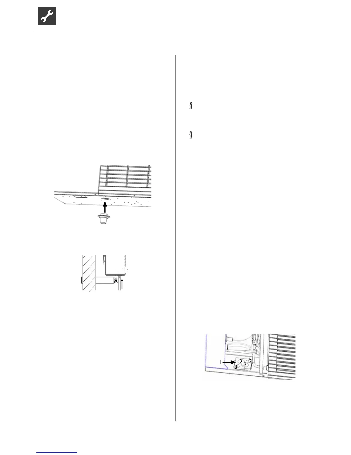
plied with. Attach the enclosed sealing plate into the
recessinthehousingoor.
1 Sealing plate
2 Heating water feed-throughs
3 Electric cable feed-throughs