Legende: 819393-2c
Technische Änderungen vorbehalten.
Alle Maße in mm.
V3 Variante 3
A Vorderansicht
C Draufsicht
V Detailansicht Verkleidung
X Detailansicht Kondensatleitung innerhalb Gebäude
Y Detailansicht Kondensatleitung außerhalb Gebäude
Z Detailansicht Bodenbefestigung
FA Fertigaußenfassade
UKG Unterkante Gerät
OKF Oberkante Fundament
LRO Leerrohr KG DN 125, Øa 125, bauseits kürzen
LR Luftrichtung
FS Freiraum für Servicezwecke
1 Heizwasservorlauf (Zubehör)
2 Heizwasserrücklauf (Zubehör)
3 Kabeldurchführung
4 Wanddurchführung (Zubehör)
5 Kondensatablauf / Syphon (Aufstellungshinweise Kondensatablauf siehe Bedienungsanleitung)
7 Konsole für Bodenbefestigung (Zubehör)
8 Verkleidung Wanddurchführung (Zubehör)
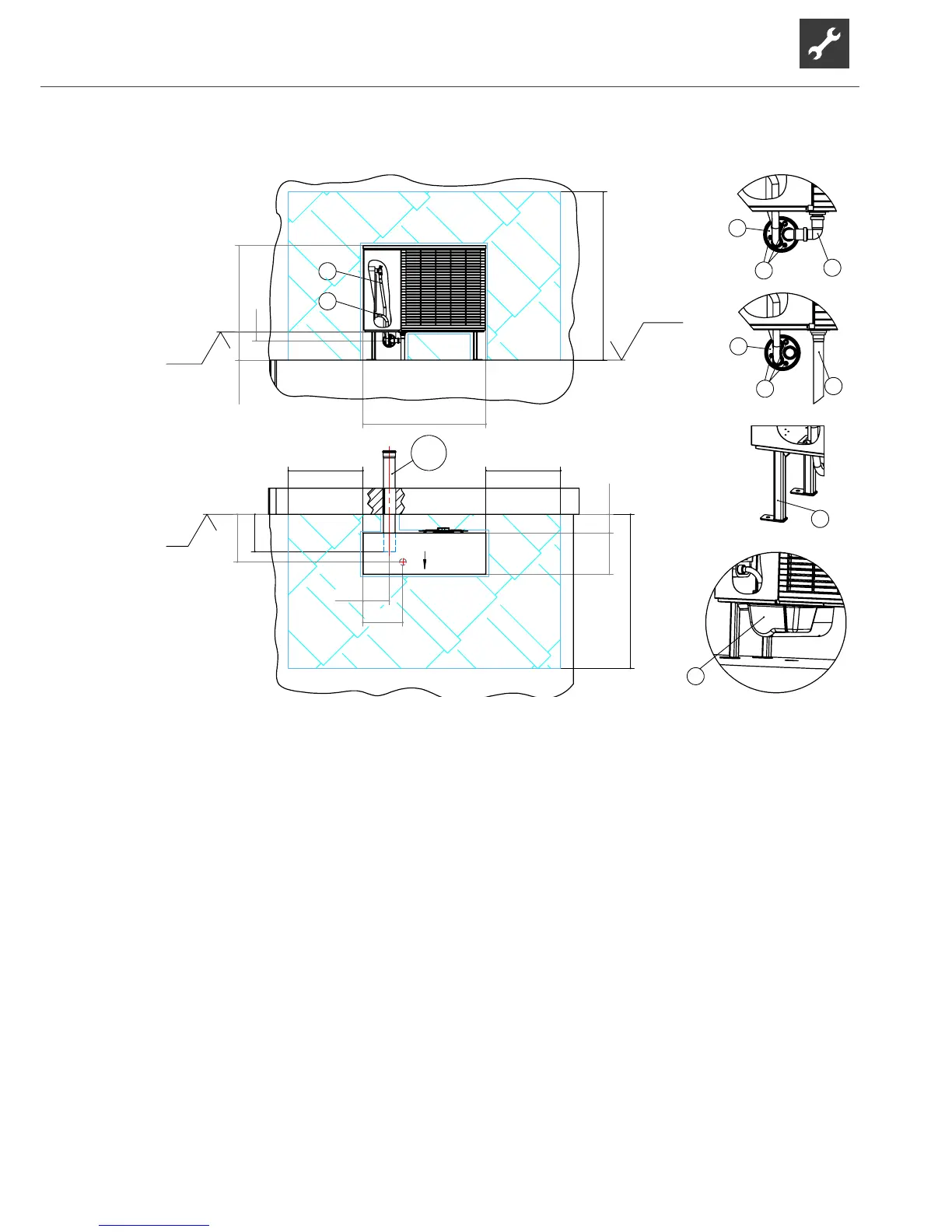
Installationplanforoorbracket
with wall duct
Key: 819393-3c
Subject to technical amendments without prior notice.
All dimensions in mm.
V3 Variant 3
A Front view
C Top view
V Detailed view of cladding
X Detailed view of condensate line inside building
Y Detailed view of condensate line outside building
Z Detailed view of oor attachment
FA Complete external facade
UKG Lower edge of device
OKF Upper edge of foundation
LRO Empty sewer conduit DN 125, Øa 125, shorten on site
LR Direction of air
FS Clearance for servicing
1 Heating water supply (accessory)
2 Heating water return (accessory)
3 Cable bushing
4 Wall duct (accessory)
5 Condensate drain/waste trap (for installation notes on condensate drain, see operation manual)
7 Bracket for oor attachment (accessory)
8 Cladding of wall duct (accessory)